Lower the work equipment to the ground.
With the engine off, turn the key to the ON position and move both hydraulic control levers to relieve hydraulic pressure.
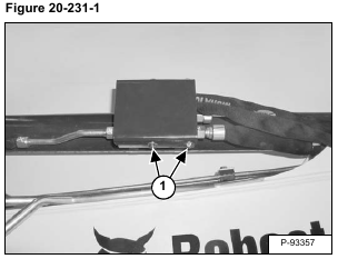
Remove the bolts (Item 1) [Figure 20-231-1].
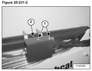
Remove the bolts (Item 1) and cover (Item 2) [Figure 20-231-2].
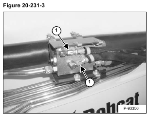
Remove the hoses (Item 1) [Figure 20-231-3].
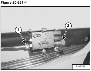
Remove the tube line (Item 1) and hose (Item 2) [Figure 20-231-4].
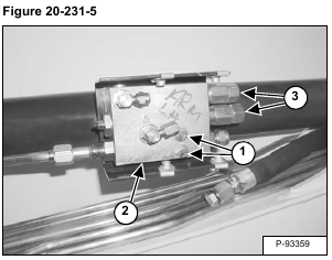
Remove the bolts (Item 1) and nuts. Remove the valve (Item 2) [Figure 20-231-5].
The lock valve is not serviceable. If the relief valves (Item 3) [Figure 20-231-5] have been tampered with, the complete valve assembly must be replaced.
