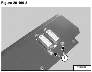
Remove the bolts (Item 1) [Figure 20-190-3] and nuts.
Remove the valve from the floor pan.
Installation: Tighten the bolts to 43 – 47 N•m (32 – 35 ft-lb) torque.
NOTE: The procedure is shown on the left travel side of the valve. The procedure is the same for both sides of the valve.
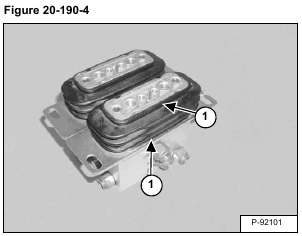
Cut and remove the cable ties (Item 1) [Figure 20-190-4].
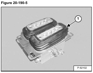
Remove the dust boot (Item 1) [Figure 20-190-5].
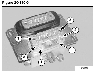
Remove the four screws (Item 1) [Figure 20-190-6] and remove the pivot assembly.
Installation: After installing the pivot assembly loosen the screws (Item 2). Turn the adjustment screws (Item 3) [Figure 20-190-6] until there is no end play in the pivot assembly.
Tighten the screws (Item 2) [Figure 20-190-6] after the adjustment is complete.
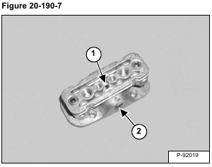
Loosen the screw (Item 1) and remove the pivot pin (Item 2) [Figure 20-190-7].
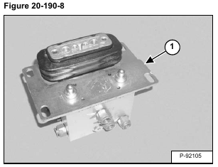
Remove the plate (Item 1) [Figure 20-190-8].
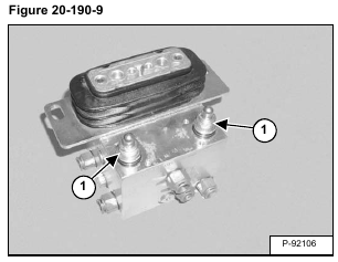
Remove the plunger assemblies (Item 1) [Figure 20-190-9].
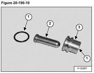
Remove the O-rings (Item 1) and plunger (Item 2) from the bushing (Item 3) [Figure 20-190-10].
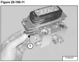
Remove the spool assemblies (Item 1) [Figure 20-190-11].
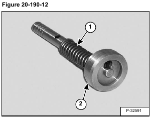
Compress the spring (Item 1) and remove the seat (Item 2) [Figure 20-190-12].
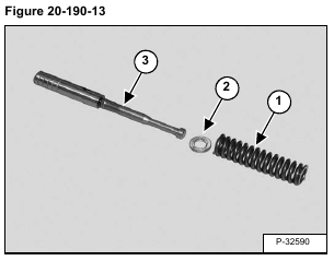
Remove the spring (Item 1) and shim (Item 2) from the spool (Item 3) [Figure 20-190-13].
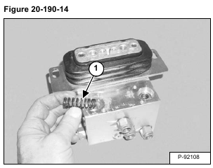
Remove the spring (Item 1) [Figure 20-190-14].
Repeat the procedure for the right travel side of the valve.
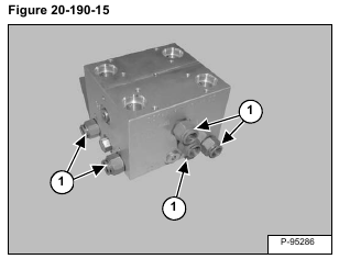
Remove the fittings (Item 1) [Figure 20-190-15].
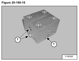
Remove the plugs (Item 1) [Figure 20-190-16].
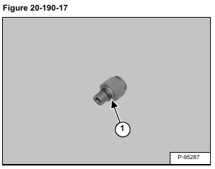
Remove the O-rings (Item 1) [Figure 20-190-17] from the fittings.
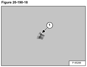
Remove the O-rings (Item 1) [Figure 20-190-18] from the plugs.
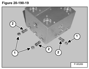
Remove the nut (Item 1) [Figure 20-190-19].
Installation: Tighten the nut to 9,8 N•m (7.2 ft-lb) torque.
Remove the spool (Item 2) [Figure 20-190-19].
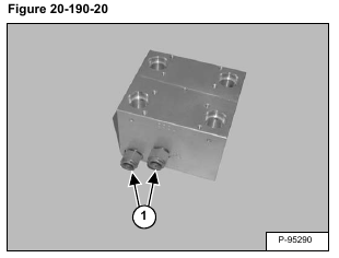
Remove the fittings (Item 1) [Figure 20-190-20].
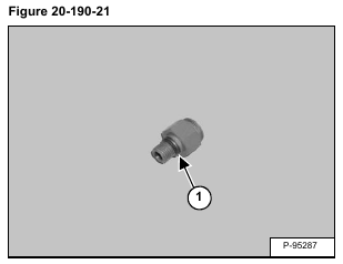
Remove the O-ring (Item 1) [Figure 20-190-21] from both fittings.
