Lift and block both sides of the machine as follows:
Raise the blade fully.
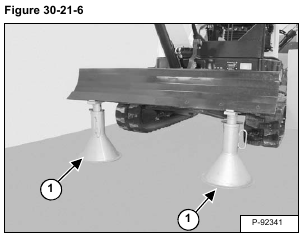
Use the boom and arm to lift the blade end of the machine up about 75 mm (3.0 in) and install jack stands (Item 1) [Figure 30-21-6] under the blade.
Raise the boom.
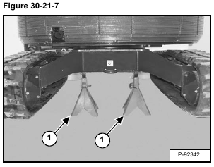
Swing the upper structure 180° and use the boom and arm to slowly lift the opposite end of the undercarriage and install jack stands under the undercarriage [Figure 30-21-7].
Raise the boom until the weight of the machine is supported by the jack stands.
Stop the engine.
Release track tension (See Adjusting Tension on Page 30-21-3.)
With the excavator raised and the bleed fitting loosened, start the excavator. (See Adjusting Tension on Page 30-21-3.)
Slowly turn the track. This will force more grease out of the grease spring.
Stop the engine.
The track can be removed either as a complete assembly or by removing a connecting pin and separating the track.
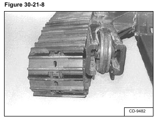
To remove the track as a compete assembly, install a pry bar between the track and the front idler wheel and pry out on the track [Figure 30-21-8].
Installation: Put the track over the drive sprocket lugs.
Then position the front of the track over the front idler wheel.
See Adjustment for adding grease to the grease spring and for checking track clearance. (See Adjusting Tension on Page 30-21-3.)
To remove the track by removing a connecting pin:
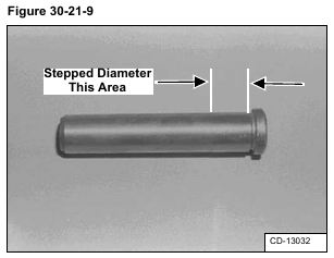
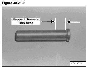
There is no master link or master connecting pin with this track. The connecting pins have a stepped diameter [Figure 30-21-9]. The smaller diameter is a slip fit into the track connecting links and the larger diameter is a press fit.
To remove a connecting pin, hold a heavy steel block on the connecting link near the pin being removed. Use a heavy hammer and a punch to drive out the connecting pin.
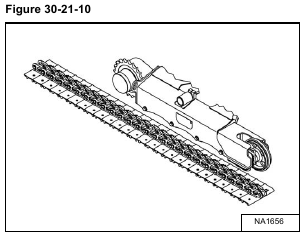
Installation: Put the steel track under the track frame so the front end of the track extends approximately three links in front of idler wheel [Figure 30-21-10].
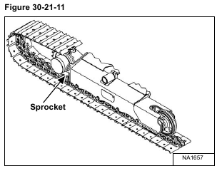
Pull the opposite end of the track up and forward and position the end links of the steel track onto the sprocket [Figure 30-21-11].
With the help of a second person, start the excavator.
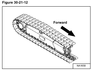
Use the travel lever (on which side the track is being installed) to slowly turn the drive motor in the forward direction. Hold the end of the track upwards as the drive motor slowly moves the track forward. Guide the end of the track over the top of the roller and up to the front idler wheel [Figure 30-21-12].
Stop the engine.
Position the two ends of the track together and use a drift pin to hold the links together.
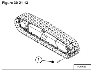
Insert the connecting link pin (Item 1) [Figure 30-21-13] into the track link hole. Tap the end of the pin until the press fit diameter contacts the connecting link hole.
Hold a heavy steel block on the back side of the track connecting link and use a hammer to drive the connecting link pin into the track link until the head of the pin is flush with the track link.
See Adjustment for adding grease to the grease spring and for checking track clearance. (See Adjusting Tension on Page 30-21-3.)
