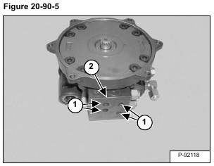
Remove the bolts (Item 1) and remove the counter balance valve (Item 2) [Figure 20-90-5].
Remove the O-rings (Item 1) [Figure 20-90-6].
Remove the plugs (Item 1). Remove the spring seat (Item 2), spring (Item 3), spool (Item 4) and spacer (Item 5) [Figure 20-90-7].
Remove the plugs (Item 6), spring (Item 7) and spool (Item 8) [Figure 20-90-7].
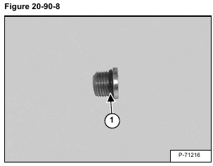
Remove the O-rings (Item 1) [Figure 20-90-8] from the plugs.
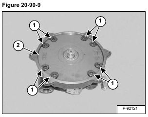
Remove the bolts (Item 1) and cover (Item 2) [Figure 20-90-9].
Remove the dowel pins (Item 1) [Figure 20-90-10].
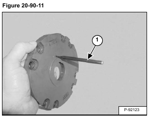
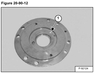
Use a punch (Item 1) [Figure 20-90-11] to push the screen (Item 1) [Figure 20-90-12] out of the cover.
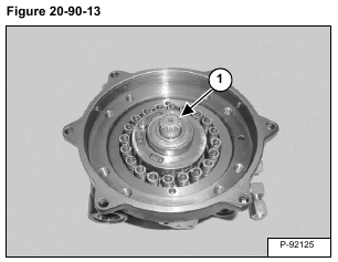
Remove the shaft / bearing assembly (Item 1) [Figure 20-90-13].
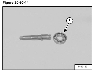
Remove the bearing (Item 1) [Figure 20-90-14] from the shaft.
Remove the swash plate (Item 1) [Figure 20-90-15].
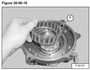
Remove the spring assembly (Item 1) [Figure 20-90-16].
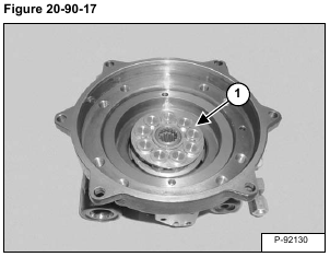
Remove the rotating group (Item 1) [Figure 20-90-17].
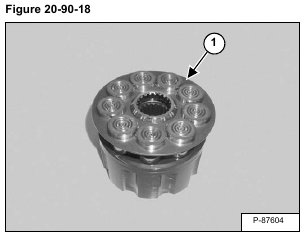
Remove the piston assemblies / retainer (Item 1) [Figure 20-90-18] from the cylinder block.
NOTE: It is not important that the pistons are installed in the original bores.
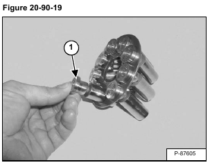
Remove the piston assemblies (Item 1) [Figure 20-90-19] from the retainer.
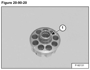
Remove the ball guide (Item 1) [Figure 20-90-20].
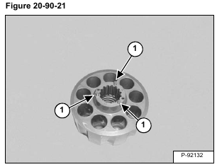
Remove the three pins (Item 1) [Figure 20-90-21].
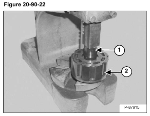
Using a press and an appropriate sized spacer (Item 1), compress the spring in the cylinder block (Item 2) [Figure 20-90-22].
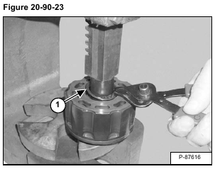
Remove the snap ring (Item 1) [Figure 20-90-23].
Remove the cylinder block from the press.
Remove the top washer (Item 1), spring (Item 2) and bottom washer (Item 3) [Figure 20-90-24].
Remove the brake piston (Item 1) [Figure 20-90-25].
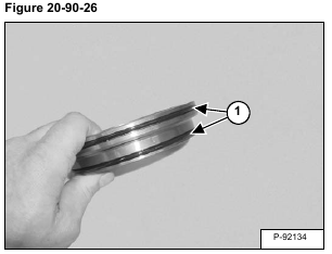
Remove the O-rings (Item 1) [Figure 20-90-26].
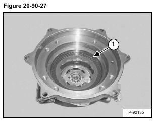
Remove the brake disk (Item 1) [Figure 20-90-27].
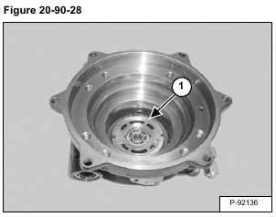
Remove the valve plate (Item 1) [Figure 20-90-28].
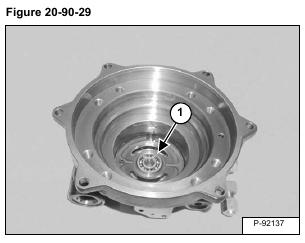
Remove the bearing (Item 1) [Figure 20-90-29].
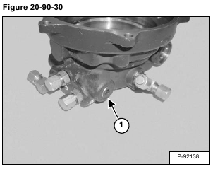
Remove the plug (Item 1) [Figure 20-90-30] from both sides of the housing.
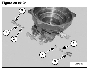
Remove the spring (Item 1) and poppet (Item 2). Remove the O-rings (Item 3) [Figure 20-90-31].
