Rotate the upperstructure so the blade is to the rear of the excavator.
Remove the arm. (See Removal And Installation on Page 40-160-1.)
Remove the boom. (See Removal And Installation on Page 40-150-1.)
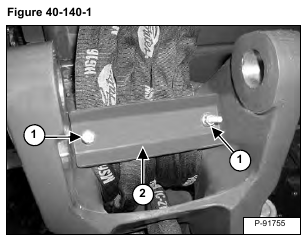
Remove the nuts (Item 1) and the clamp (Item 2) [Figure 40-140-1].
NOTE: Before the hoses are removed from the clamped position, the hoses must be measured for correct clamped length and position. (See Boom Swing Frame Hose Routing on Page 40-140-5.)
NOTE: Later model excavators are not equipped with the clamp (Item 2) [Figure 40-140-1].
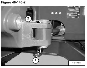
Remove the snap ring (Item 1), washer, and pin (Item 2) [Figure 40-140-2] from the rod end of the swing cylinder.
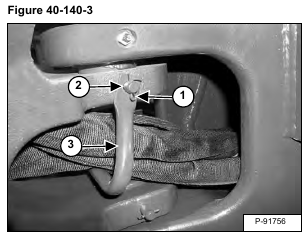
Remove the cotter pin (Item 1), retaining pin (Item 2) and hose bracket (Item 3) [Figure 40-140-3].
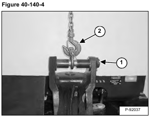
Install the boom pin (Item 1) using spacers to position a lifting clevis (Item 2) [Figure 40-140-4] on the center of the boom pin.
NOTE: The spacers will prevent the clevis from sliding on the boom pin causing the swing frame to tip from side to side.
Support the bottom pin with a jack.
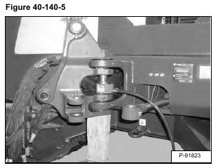
Install a porta-power between the top and bottom pins and press the top pin out [Figure 40-140-5].
Remove the cotter pin (Item 1) and retaining pin (Item 2) [Figure 40-140-6].
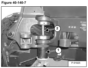
Install a spacer tube (Item 1) [Figure 40-140-7] and jack under the swing frame to support the casting. The spacer tube must be large enough to allow the pin to be driven in the center of the spacer tube for pin removal.
Use a large punch (Item 2) [Figure 40-140-7] and drive the bottom swing frame pin out.
NOTE: Do not use a porta-power to press out the bottom pin because the top casting cannot be supported and possible damage to the casting could occur.
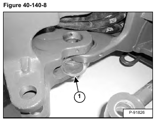
Remove the bottom spacer (Item 1) [Figure 40-140-8] from the swing frame.
Remove the swing frame.
Inspect the bushings for damage. Replace damaged bushings as necessary. (See Bushing Removal on Page 40-140-6.)
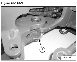
Installation: Install the bottom spacer (Item 1) [Figure 40-140-9] on the swing frame. Install the swing frame.
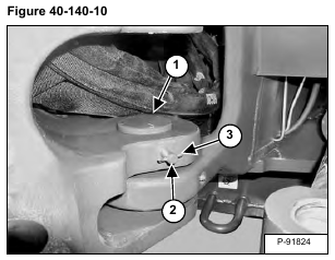
Installation: Align the boom swing frame and install the lower pivot pin (Item 1). Install the retaining pin (Item 2) and cotter pin (Item 3) [Figure 40-140-10]. Lift up on the boom swing frame.
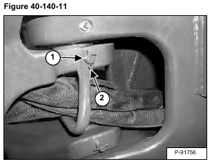
Installation: Install the top pivot pin, retaining pin (Item 1) and cotter pin (Item 2) [Figure 40-140-11].
