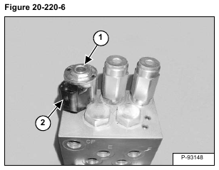
Remove the nut (Item 1) and coil (Item 2) [Figure 20-220-6].
Installation: Tighten the nut to 5 – 8 N•m (4 – 6 ft-lb) torque.
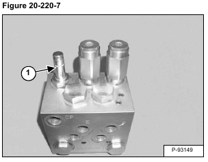
Remove the solenoid (Item 1) [Figure 20-220-7].
Installation: Tighten the solenoid to 41 – 47 N•m (30 – 35 ft-lb) torque.
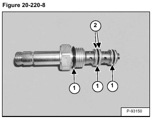
Remove the O-rings (Item 1) and back-up rings (Item 2) [Figure 20-220-8].
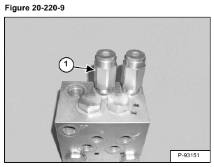
Remove the valve (Item 1) [Figure 20-220-9].
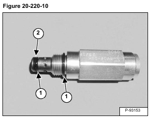
Remove the O-rings (Item 1) and back-up ring (Item 2) [Figure 20-220-10].
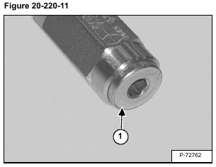
Remove the plug (Item 1) [Figure 20-220-11].
Installation: Tighten the plug to 27,1 N•m (20 ft-lb) torque.
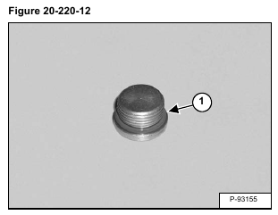
Remove the O-ring (Item 1) [Figure 20-220-12]
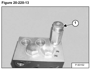
Remove the valve (Item 1) [Figure 20-220-13].
Installation: Tighten the valve to 41 – 47 N•m (30 – 35 ft-lb) torque.
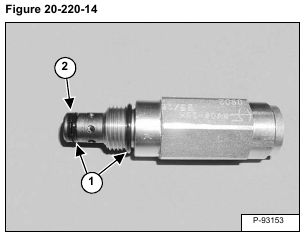
Remove the O-ring (Item 1) and back-up rings (Item 2) [Figure 20-220-14].
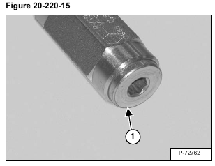
Remove the plug (Item 1) [Figure 20-220-15].
Tighten the plug to 27,1 N•m (20 ft-lb) torque.
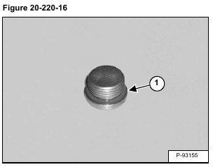
Remove the O-ring (Item 1) [Figure 20-220-16].
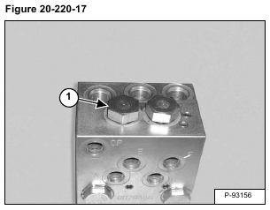
Remove the plug (Item 1) [Figure 20-220-17].
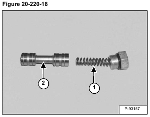
Remove the spring (Item 1) and spool (Item 2) [Figure 20-220-18].
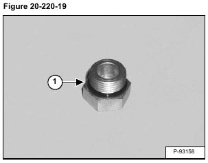
Remove the O-ring (Item 1) [Figure 20-220-19].
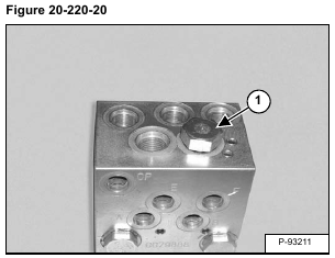
Remove the plug (Item 1) [Figure 20-220-20].
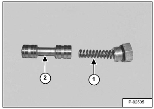
Remove the spring (Item 1) and spool (Item 2) [Figure 20-220-21].
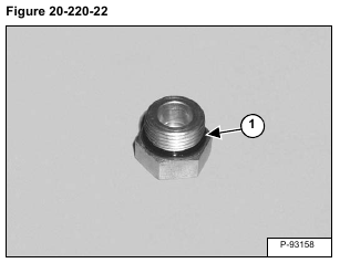
Remove the O-ring (Item 1) [Figure 20-220-22].
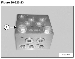
Remove the check valve (Item 1) [Figure 20-220-23].
Tighten the check valve to 41 – 47 N•m (30 – 35 ft-lb) torque.
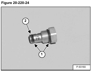
Remove the O-rings (Item 1) and back-up ring (Item 2) [Figure 20-220-24].
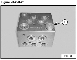
Remove the check valve (Item 1) [Figure 20-220-25].
Tighten the check valve to 41 – 47 N•m (30 – 35 ft-lb) torque.
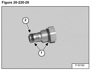
Remove the O-rings (Item 1) and back-up ring (Item 2) [Figure 20-220-26].
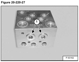
Remove the plugs (Item 1) [Figure 20-220-27].
Remove the O-rings (Item 1) [Figure 20-220-28].
Clean all parts in solvent and dry with compressed air.
Inspect all parts for wear or damage. Replace any worn or damaged parts.
Always install new O-rings. Lubricate the O-rings with clean hydraulic fluid before installation.
