Remove the left console cover. (See Console Removal And Installation on Page 40-60-7.)
Disconnect the wire harness (Item 1) [Figure 20-120-4].
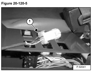
Remove the lock (Item 1) [Figure 20-120-5] from the electrical connector.
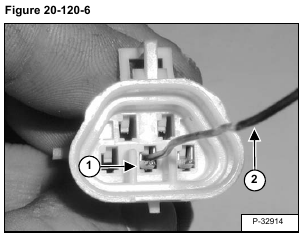
Using a small piece of wire, depress the wire terminal tabs (Item 1) [Figure 20-120-6].
Carefully remove the individual wires from the back of the electrical connector.
Remove the control handle (joystick) assembly from the excavator.
Installation: Use a small piece of wire and rebend the tab on each wire before installing it in the electrical connector.
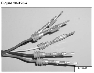
Installation: The wires [Figure 20-120-7] must be installed in the proper locations in the wire connector, listed below.
Check each wire to be certain the tab locks into position.
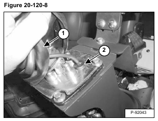
Raise the boot (Item 1) and pull the grommet (Item 2) up [Figure 20-120-8] out of the housing.
Remove the wire and grommet.
Pull the boot down and pull the wire harness (Item 1) out of the boot. Loosen the nut (Item 2) [Figure 20-120-9] and remove the handle.
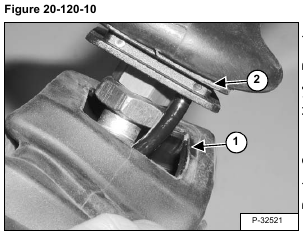
Installation: Align the top of the dust boot (Item 1) with the groove (Item 2) [Figure 20-120-10].

