Clean the outside of the manifold assembly / accumulator before disassembly.
Remove the accumulator (Item 1) [Figure 20-61-5] from the valve body.
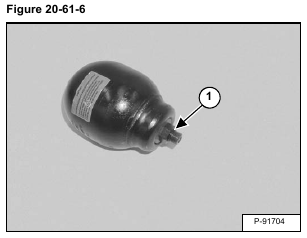
Remove the O-ring (Item 1) [Figure 20-61-6].
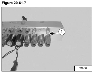
Remove the screws (Item 1) [Figure 20-61-7].
Installation: Tighten the screws to 3 N•m (27 in-lb) torque.
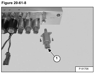
Remove the solenoid (Item 1) [Figure 20-61-8].
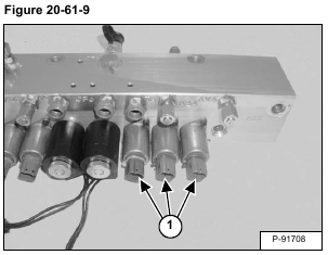
Repeat the procedure for the three solenoid (Item 1) [Figure 20-61-9].
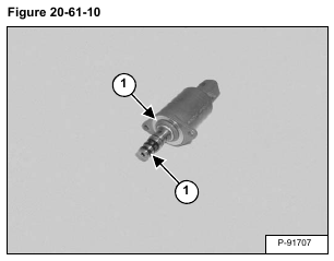
Remove the O-rings (Item 1) [Figure 20-61-10] from the solenoids.
Remove the nut (Item 1) [Figure 20-61-11].
Installation: Tighten the nut to 4,1 – 6,1 N•m (36 – 54 in-lb) torque.
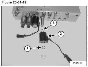
Remove the O-ring (Item 1), coil (Item 2) and O-ring (item 3) [Figure 20-61-12].
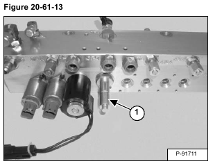
Remove the spool (Item 1) [Figure 20-61-13].
Installation: Tighten the spool to 30 N•m (22 ft-lb) torque.
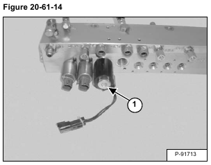
Remove the nut (Item 1) [Figure 20-61-14].
Installation: Tighten the nut to 4,1 – 6,1 N•m (36 – 54 in-lb) torque.
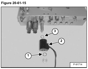
Remove the O-ring (Item 1), coil (Item 2) and O-ring (Item 3) [Figure 20-61-15].
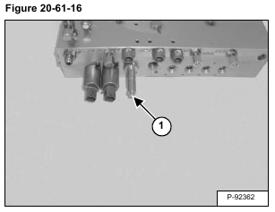
Remove the spool (Item 1) [Figure 20-61-16].
Installation: Tighten the spool to 30 N•m (22 ft-lb) torque.
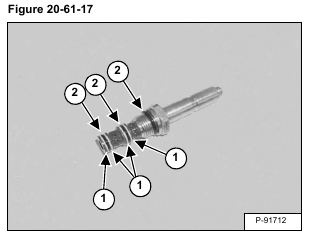
Remove the back-up rings (Item 1) and O-rings (Item 2) [Figure 20-61-17] from both spools.
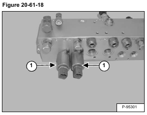
Remove the screws and solenoids (Item 1) [Figure 20-61-18].
Installation: Tighten the screws to 3 N•m (27 in-lb) torque.
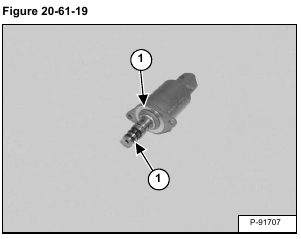
Remove the O-rings (Item 1) [Figure 20-61-19].
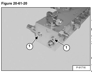
Remove the plugs (Item 1) [Figure 20-61-20].
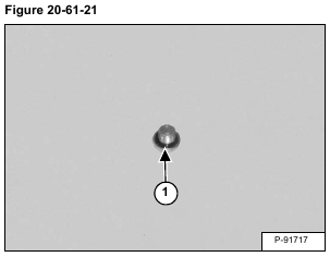
Remove the O-ring (Item 1) [Figure 20-61-21] from both plugs.
Remove the check valve assembly (Item 1) [Figure 20-61-22].
Installation: Tighten the plug to 40 N•m (29 ft-lb) torque.
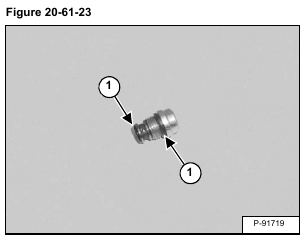
Remove the O-rings (Item 1) [Figure 20-61-23].
Remove the plug (Item 1) [Figure 20-61-24].
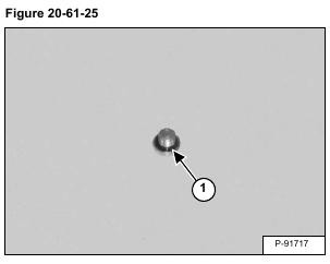
Remove the O-ring (Item 1) [Figure 20-61-25] from the plug.
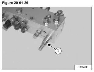
Remove the pilot relief valve (Item 1) [Figure 20-61-26].
Installation: Tighten the pilot relief valve to 30 N•m (22 ft-lb) torque.
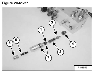
Remove the spring seat (Item 1), spring (Item 2), spring seat (Item 3) and seat (Item 4). Remove the cap (Item 5) and remove the adjustment screw (Item 6). Remove the O-rings (Item 7) [Figure 20-61-27].
Clean all parts in solvent and dry with compressed air.
Inspect all parts for wear or damage. Replace any worn or damaged parts.
Always install new seals and O-rings. Lubricate all seals and O-rings with clean hydraulic fluid before installation.

