Clean the outside of the hydraulic X-Change manifold before disassembly.
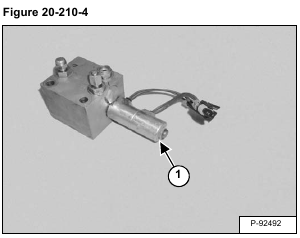
Remove the nut (Item 1) [Figure 20-210-4].
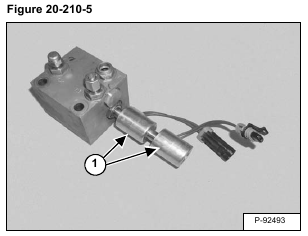
Remove the two solenoids (Item 1) [Figure 20-210-5].
NOTE: Mark the solenoids for correct assembly.
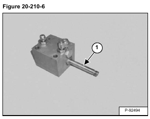
Remove the spool (Item 1) [Figure 20-210-6].
Remove the O-ring (Item 1) [Figure 20-210-7] from the spool.
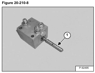
Remove the actuator assembly (Item 1) [Figure 20-210-8].
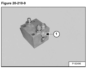
Remove the plug (Item 1) [Figure 20-210-9].
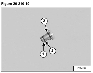
Remove the back-up ring (Item 1) and O-rings (Item 2) [Figure 20-210-10].
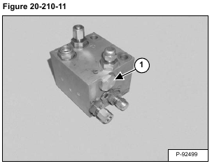
Remove the plug (Item 1) [Figure 20-210-11].
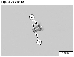
Remove the back-up ring (Item 1) and O-rings (Item 2) [Figure 20-210-12].
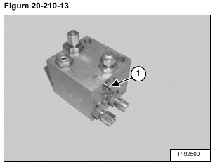
Remove the spool (Item 1) [Figure 20-210-13].
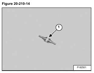
Remove the rings (Item 1) [Figure 20-210-14].
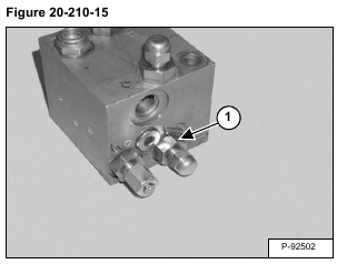
Remove the fitting (Item 1) [Figure 20-210-15] from the “S” port.
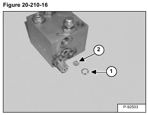
Remove the snap ring (Item 1) and screen (Item 2) [Figure 20-210-16] from the “S” port.
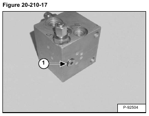
Remove the plug (Item 1) [Figure 20-210-17].
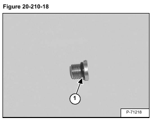
Remove the O-ring (Item 1) [Figure 20-210-18] from the plug.
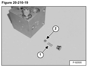
Remove the spring (Item 1) and ball (Item 2) [Figure 20-210-19] from the manifold.
Clean all parts in solvent and dry with compressed air.
Inspect all parts for wear or damage. Replace any worn or damaged parts.
Always install new seals and O-rings. Lubricate all seals and O-rings with clean hydraulic fluid before installation.
