Clean the outside of the hydraulic pump before disassembly.
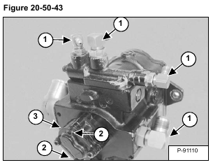
Remove the fittings (Item 1). Remove the two bolts (Item 2) and remove the gear pump (Item 3) [Figure 20-50-43].
Installation: Tighten the bolts to 26 – 32 N•m (19 – 24 ft-lb) torque.
Remove the two bolts (Item 1), inlet housing (Item 2) [Figure 20-50-44] and O-ring.
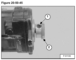
Remove the bolt (Item 1) and coupler (Item 2) [Figure 20-50-45].
Installation: See Coupler Removal And Installation.
(See Coupler Removal And Installation on Page 20-50-12.)
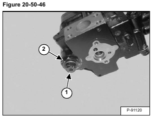
Measure and record the height of the adjustment screw (Item 1). Loosen the lock nut (Item 2) [Figure 20-50-46] and remove the adjustment screw.
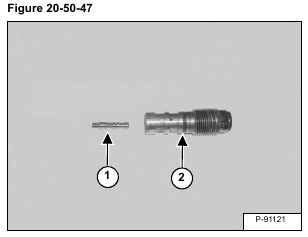
Remove the spool (Item 1) and O-ring (Item 2) [Figure 20-50-47].
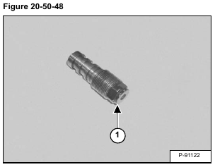
Remove the plug (Item 1) [Figure 20-50-48].
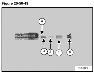
Remove the collar (Item 1), pin (Item 2), and servo piston (Item 3). Remove the O-rings (Item 4) [Figure 20-50-49].
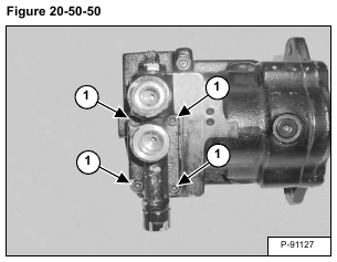
Remove the four bolts (Item 1) [Figure 20-50-50] and remove the control.
Installation: Tighten the bolts to 11,4 – 13,9 N•m (8.4 -10.3 ft-lb) torque.
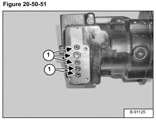
Remove the five O-rings (Item 1) [Figure 20-50-51].
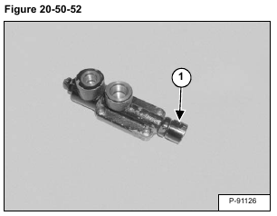
Remove fitting (Item 1) [Figure 20-50-52].
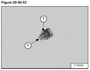
Remove the O-ring (Item 1) from the fitting. Inspect the orifice (Item 2) [Figure 20-50-53] for damage and contamination.
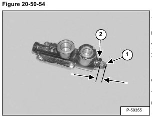
Measure and record the length of the adjustment screw (Item 1). Loosen the lock nut (Item 2) [Figure 20-50-54] and remove the adjustment assembly.
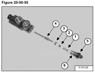
Remove the spring (Item 1), spring seat (Item 2), bushing (Item 3) and spool (Item 4) [Figure 20-50-55].
Installation: With the lock nut (Item 5) loose, tighten the body (Item 6) [Figure 20-50-55] until it bottoms out in the control.
Remove the small adjustment screw (Item 1). Remove the bushing (Item 2). Remove the O-rings (Item 3) [Figure 20-50-56].
Remove the orifice (Item 1) [Figure 20-50-57].
Installation: Tighten the PC orifice to 2,2 – 2,7 N•m (20 -24 in-lb) torque.
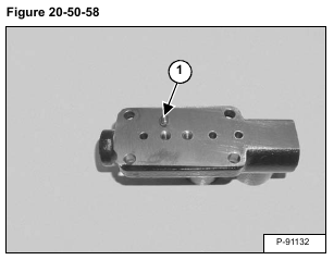
Inspect the orifice (Item 1) [Figure 20-50-58] for damage and contamination.
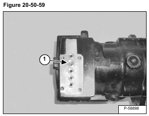
Remove the FINE CONTROL orifice (Item 1) [Figure 20-50-59].
Installation: Tighten the orifice to 2,2 – 2,7 N•m (20 – 24 in-lb) torque.
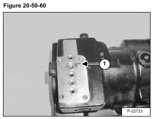
Inspect the orifice (Item 1) [Figure 20-50-60] for damage and contamination.
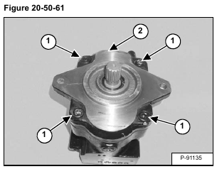
Stand the pump shaft end up. Remove the four bolts (Item 1) and flange (Item 2) [Figure 20-50-61].
Installation: Tighten the bolts to 96,2 – 117,6 N•m (71 – 86.7 ft-lb) torque.
Remove the snap ring (Item 1) [Figure 20-50-62].
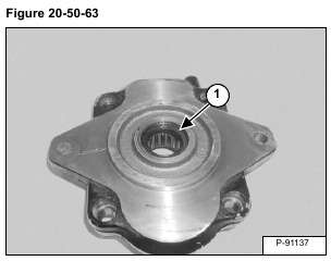
Remove the oil seal (Item 1) [Figure 20-50-63].
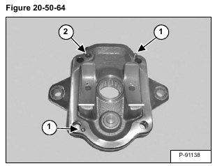
Remove the dowel pins (Item 1) and O-ring (Item 2) [Figure 20-50-64].
NOTE: The dowel pins may stay in either the housing or flange during disassembly.
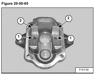
Remove screws (Item 1) and remove the bushings (Item 2) [Figure 20-50-65].
Installation: Tighten the screws to 5,3 – 6,5 N•m (47 – 58 in-lb) torque.
When installing the bushing, the oil hole (Item 1) in the bushing must be aligned with the oil hole (Item 2) [Figure 20-50-66] in the flange.
Remove the needle bearing (Item 1) and stop (Item 2) [Figure 20-50-67].
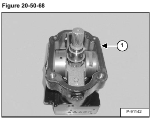
Remove the gasket (Item 1) [Figure 20-50-68].
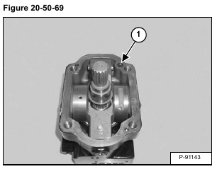
Remove the O-ring (Item 1) [Figure 20-50-69].
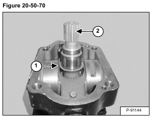
Remove the thrust washer (Item 1) and shaft (Item 2) [Figure 20-50-70].
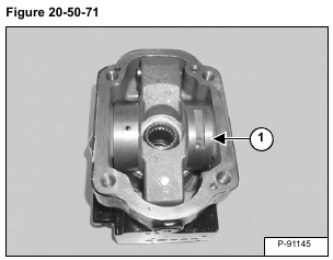
Remove the swash plate (Item 1) [Figure 20-50-71].
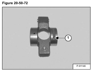
Remove the orifice (Item 1) [Figure 20-50-72].
Installation: Tighten the orifice to 2,2 – 2,7 N•m (20 – 24 in-lb) torque.
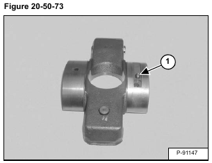
Inspect the orifice (Item 1) [Figure 20-50-73] for damage and contamination.
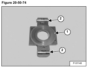
Inspect the face (Item 1) and pins (Item 2) [Figure 20-50-74] of the swash plate.
Remove the rotating group (Item 1) [Figure 20-50-75].
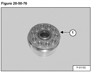
Remove the piston / retainer assembly (Item 1) [Figure 20-50-76].
Remove the pistons (Item 1) [Figure 20-50-77] from the retainer.
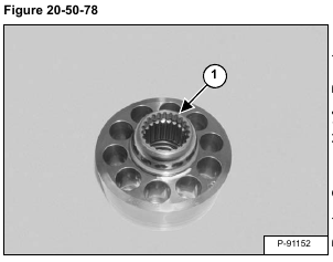
Remove the retainer guide [Figure 20-50-78].
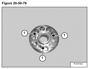
Remove the three pins (Item 1) [Figure 20-50-79].
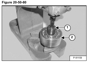
Using a press and an appropriate sized spacer (Item 1), compress the spring in the cylinder block (Item 2) [Figure 20-50-80].
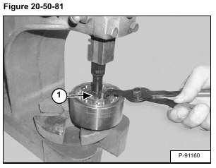
Remove the snap ring (Item 1) [Figure 20-50-81].
Remove the cylinder block from the press.
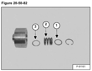
Remove the top washer (Item 1), spring (Item 2) and bottom washer (Item 3) [Figure 20-50-82].
Remove the valve plate (Item 1) and thrust washer (Item 2) [Figure 20-50-83].
Remove the piston (Item 1) and valve plate dowel pin (Item 2) [Figure 20-50-84].
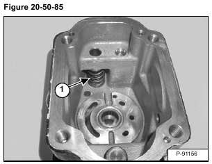
Slightly compress and remove the spring assembly (Item 1) [Figure 20-50-85].
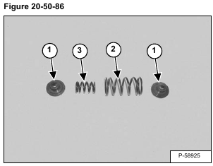
Remove the spring seats (Item 1), large spring (Item 2) and small spring (Item 3) [Figure 20-50-86].
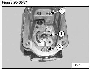
Remove the piston (Item 1). Remove the destroking piston (Item 2). Remove the needle bearing (Item 3) [Figure 20-50-87].
