Remove the air cleaner. (See Removal And Installation on Page 60-40-1.)
Remove the fuel shut-off solenoid. (See Fuel Shut-off Solenoid Removal And Installation on Page 60-70-2.)
Disconnect the negative (-) cable from the battery.
Clean around the injection pump.
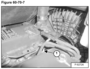
Remove the nut and wire harness (Item 1) [Figure 60-70-7] from the right glow plug.
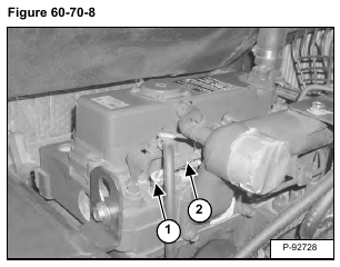
Remove the nuts (Item 1) from the two remaining glow plugs. Remove the strap (Item 2) [Figure 60-70-8] from the glow plugs.
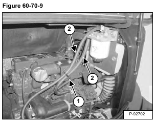
Cut and remove the tie strap (Item 1). Remove the fuel lines (Item 2) [Figure 60-70-9].
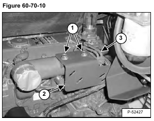
Remove the bolts (Item 1) and bracket (Item 2) [Figure 60-70-10].
Disconnect the high pressure fuel lines (Item 3) [Figure 60-70-10] from the fuel injectors and fuel injection pump.
Remove the high idle body (Item 1) [Figure 60-70-11].
Installation: Tighten the high idle body to 44 – 49 N•m (33 – 36 ft-lb) torque.
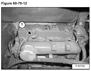
Remove the hose (Item 1) [Figure 60-70-12].
Remove the bolts (Item 1) and remove the intake manifold (Item 2) [Figure 60-70-13].
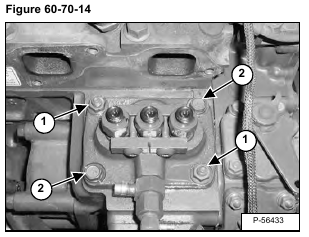
Remove the nuts (Item 1) and bolts (Item 2) [Figure 60-70-14].
Remove the injection pump.
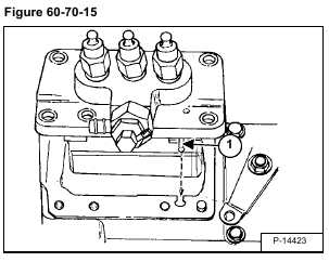
Installation: When the injection pump is installed, the rack pin (Item 1) [Figure 60-70-15] must be aligned with the slot in the engine block and positioned on the left side of the fork lever.
If the rack pin is not installed correctly engine damage can result.
NOTE: Make sure the same number of shims with the same thickness are installed under the injection pump. The shims are used for engine timing.
