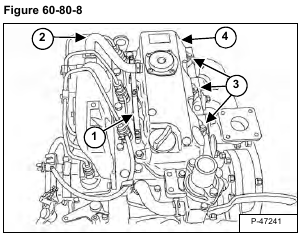
Remove the glow plug lead (Item 1), breather hose (Item 2), and valve cover bolts (Item 3) [Figure 60-80-8].
Remove the valve cover (Item 4) [Figure 60-80-8] and gasket.
Installation: Tighten the valve cover bolts to 7 – 11 N•m (5 – 8 ft-lb).
Loosen the bolts on the clamps (Item 1) and remove the injection tubes (Item 2) [Figure 60-80-9].
Tighten the injection tube nuts to 15 – 24 N•m (11 – 18 ft-lb) torque.
Remove the overflow tube assembly.
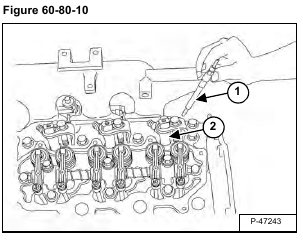
Remove the glow plugs (Item 1) and fuel injector holder assemblies (Item 2) [Figure 60-80-10].
Installation: Tighten the glow plugs to 20 – 24 N•m (15 – 18 ft-lb) torque.
Tighten the injector holders to 26 – 29 N•m (19 – 22 ft-lb) torque.
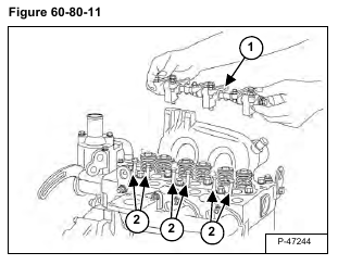
Remove the rocker arm bolts and remove the rocker arm assembly (Item 1) [Figure 60-80-11].
Installation: Tighten the bolts to 24 – 27 N•m (18 – 20 ft-lb) torque.
Remove the pushrods (Item 2) [Figure 60-80-11].
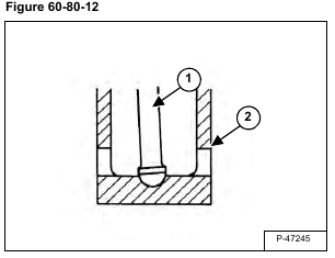
Installation: The push rod (Item 1) must be seated in the tappet (Item 2) [Figure 60-80-12] correctly or the push rods will be damaged.
After installing the rocker arm assembly and push rods, the valve lash must be adjusted. (See Valve Clearance Adjustment on Page 60-80-3.)
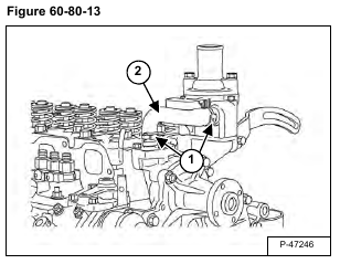
Remove the clamps (Item 1) and remove the hose (Item 2) [Figure 60-80-13].
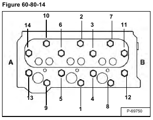
Remove the cylinder head bolts in order of #14 to #1 [Figure 60-80-14].
NOTE: (A) is the gearcase side, (B) is the flywheel side.
Installation: Put oil on the bolt threads. Tighten the bolts in the correct sequence in order of #1 to #14 to 93 – 98 N•m (69 – 72 ft-lb) torque.
NOTE: Re-tighten the cylinder head bolts in the correct sequence after the engine has been run for 30 minutes.
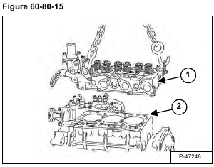
Remove the cylinder head (Item 1) and gasket (Item 2) [Figure 60-80-15].
When replacing just the gasket, use a new gasket that has the same mark (Item 1) [Figure 60-80-16] as the original gasket.
When replacing the gasket after an engine rebuild, the piston protrusion must be measured. (See Cylinder Head Top Clearance on Page 60-80-8.)
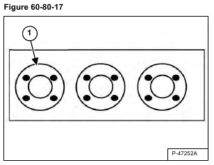
Measure and record the protrusion of each piston in the four places shown (Item 1) [Figure 60-80-17]. Find the average of each piston, then find the combined average of the three pistons.
Select the correct gasket size (thickness) from the chart [Figure 60-80-18].
Find the measurement of the highest piston protrusion and the lowest piston protrusion (recorded earlier) for each piston.
If the highest measurement exceeds the piston protrusion of the selected gasket, use the gasket which is one size larger. If the measurement exceeds gasket size 35, the engine must be disassembled, clearances checked, and reassembled.
If the measurement is two sizes smaller than the selected gasket or smaller than gasket size 15, the engine must be disassembled, clearances checked, and reassembled.
After the gasket and cylinder head have been installed, turn the crankshaft by hand to be sure there is no interference between the piston, cylinder, and valves.
