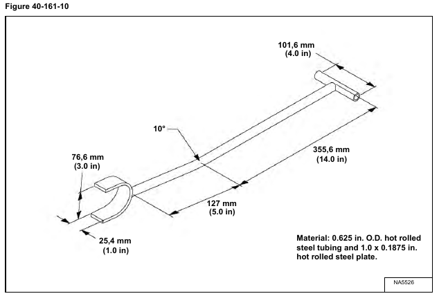
Build the service tool to assist in aligning the rod end of the cylinder between the left and right rod end pin boss.
Use the dimensions shown [Figure 40-161-10] to build the service tool.
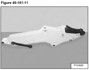
Position the arm on the ground as shown [Figure 40-161-11].
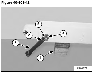
Install blocks (Item 1) [Figure 40-161-12] under the bucket end of the arm until the arm is level.
Remove the nuts (Item 2), bolt (Item 3) and link (Item 4) [Figure 40-161-12].
Remove the pin (Item 5) [Figure 40-161-12].
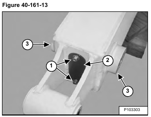
Installation: Remove the bolts (Item 1) and cover (Item 2) to gain access to the extendable arm cylinder rod end.
Use the tool [Figure 40-161-10 on Page 4] to align the rod end pin boss of the cylinder between the left and right pin boss (Item 3) [Figure 40-161-13] of the outer arm.
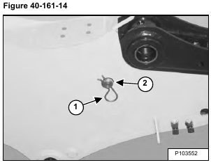
Remove the retainer (Item 1) and pin (Item 2) [Figure 40-161-14].
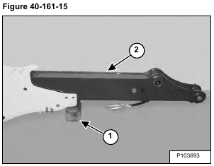
Install blocks (Item 1) under the arm. Slide the inner arm (Item 2) [Figure 40-161-15] out of the outer arm until the wear pads on the inner arm contact the wear pads on the outer arm.
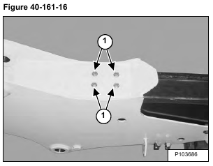
Remove the bolts (Item 1) [Figure 40-161-17] and washers.
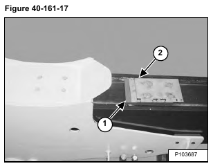
Remove the wear pad (Item 1) and shims (Item 2) [Figure 40-161-17].
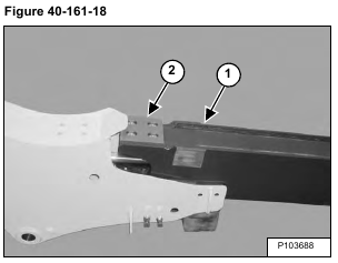
Slide the inner arm (Item 1) out until the wear pad (Item 2) [Figure 40-161-18] is exposed.
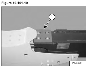
Remove the bolts from the wear pad (Item 1) [Figure 40-161-19].
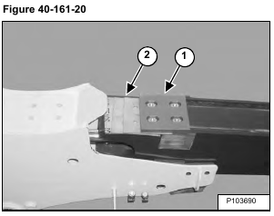
Remove the wear pad (Item 1) and shims (Item 2) [Figure 40-161-20].
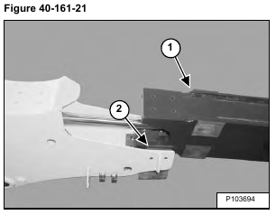
Raise the end of the inner arm and slide the arm (Item 1) out past the side wear pads (Item 2) [Figure 40-161-21].
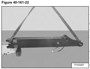
Install a hoist on the inner arm and remove the arm [Figure 40-161-22]
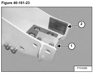
Remove the wear pad and shims (Item 1). Repeat the procedure for the opposite wear pad (Item 2) [Figure 40-161-23].
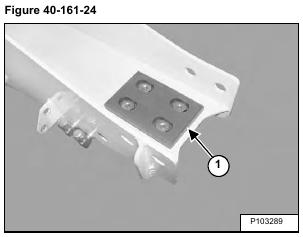
Remove the bolts from the wear pad (Item 1) [Figure 40-161-24].
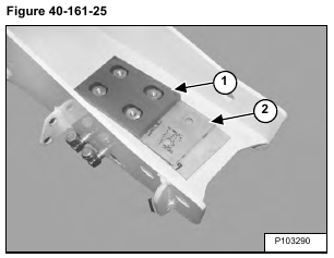
Remove the wear pad (Item 1) and shims (Item 2) [Figure 40-161-25].
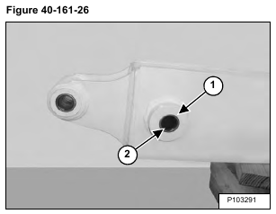
Remove the seals (Item 1) [Figure 40-161-26] from both sides of the arm.
Remove the bushings (Item 2) [Figure 40-161-26] from both sides of the arm.
Install the new bushings in the arm.
NOTE: When installing the bushings, place a steel block between the left and right bushing boss to prevent damage to the outer arm.
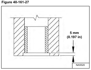
Install the bushings until they are seated 5 mm (0.197 in) in the pin boss [Figure 40-161-27].
Install new seals on both sides of the arm.
NOTE: The metal side of the seals must face outward.
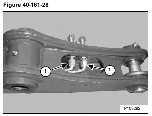
Remove the hoses (Item 1) [Figure 40-161-28] from the bulkhead fittings.
NOTE: The hoses will be removed with the cylinder.
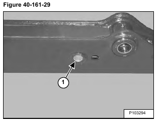
Remove the snap ring (Item 1) [Figure 40-161-29].
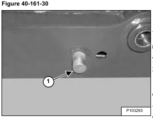
Remove the cylinder base end pin (Item 1) [Figure 40-161-30].
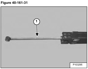
Remove the cylinder (Item 1) [Figure 40-161-31].
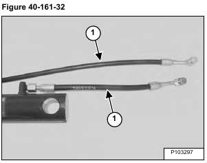
NOTE: Install the hoses (Item 1) [Figure 40-161-32] as shown to align the hoses with the bulkhead fittings on the inner arm assembly. Hose orientation can not be changed after the cylinder is installed. Install the cylinder with the hoses facing up, towards the bucket cylinder.
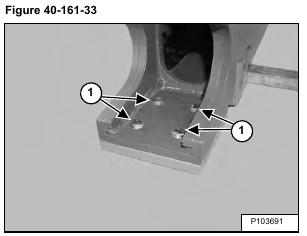
Remove the bolts (Item 1) [Figure 40-161-33].
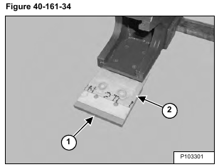
Remove the wear pad (Item 1) and shims (Item 2) [Figure 40-161-34].
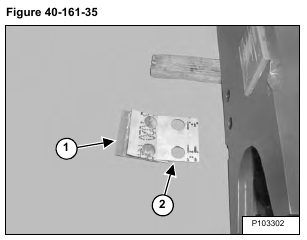
Remove the wear pad (Item 1) and shims (Item 2) [Figure 40-161-35].
Repeat the procedure for the opposite wear pad.
