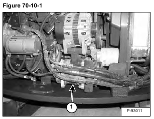
Compressor: The compressor (Item 1) [Figure 70-10-1] is the pump that circulates the refrigerant throughout the system. It raises the pressure of the refrigerant for heat transfer through the condenser and evaporator.
NOTE: The A/C system (Compressor) is recommended to be turned on for at least 5 minutes weekly throughout the year to lubricate the internal components.
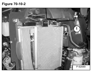
Condenser: The condenser (Item 1) [Figure 70-10-2] is the unit that receives the high pressure, high temperature refrigerant vapor from the compressor and condenses it into a high temperature liquid.
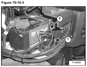
Receiver / Drier: The receiver / drier (Item 1) [Figure 70-10-3] is the unit that receives the liquid refrigerant from the condenser and removes moisture and foreign matter from the system. It also serves as a storage tank for the extra liquid refrigerant until it is needed by the evaporator.
Pressure Relief Valve: The pressure relief valve (Item 2) [Figure 70-10-3] is located on the receiver / drier assembly. This small brass valve is a safety feature that is designed to open and release the A/C charge if the pressure reaches 3344 – 3792 kPa (33,4 – 38 bar) (485 – 550 psi).
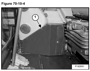
Evaporator / Heater Unit: The evaporator / heater unit (Item 1) [Figure 70-10-4] is located in the excavator cab. The unit delivers cold air for the A/C and warm air for heat into the cab. The unit contains the blower, heater coil, evaporator coil, and thermostat.
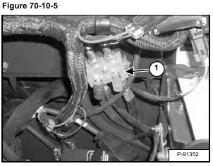
Expansion Valve: The expansion valve (Item 1) [Figure 70-10-5] controls the amount of refrigerant entering the evaporator coil.
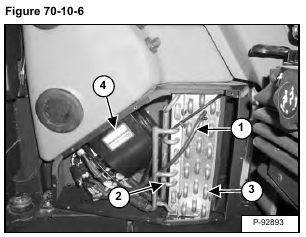
Thermostat: The thermostat (Item 1) [Figure 70-10-6] controls the temperature of the evaporator coil.
Heater Coil: The heater coil (Item 2) [Figure 70-10-6] supplies the warm air into the cab by passing air through the coil.
Evaporator Coil: The evaporator coil (Item 3) [Figure 70-10-6] cools and dehumidifies the air before it enters the cab.
Heater / Evaporator Blower: The blower (Item 4) [Figure 70-10-6] is used to push air through the heater and evaporator coils and into the cab.
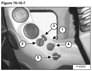
Control Panel: The panel (Item 1) [Figure 70-10-7] has four separate components.
Fan Switch: This is a four position rotary switch (Item 2) [Figure 70-10-7]. When the fan switch is in the off position the A/C will not engage, but the heat valve will operate, as it is controlled by the ignition power.
A/C Switch: The rocker switch (Item 3) [Figure 70-10-7] will be illuminated when the A/C is engaged.
Potentiometer: The potentiometer (Item 4) [Figure 70-10-7] controls the Heat Valve from fully Off to fully On.
This can be used in conjunction with the A/C for defrost of the windows and temperature control.
Fresh Air Control: The fresh air control (Item 5) [Figure 70-10-7] opens a ventilation door and allows fresh air to be drawn in to the cab.
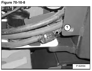
Heater Valve: The heater valve (Item 1) [Figure 70-10-8] is used to control the amount of engine coolant that flows to the heater coil.
The heater valve is located in front of the battery.
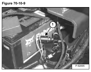
High Pressure Switch: The high pressure switch (Item 1) [Figure 70-10-9] will disengage the compressor clutch at high pressure readings over 2689 – 2827 kPa (26,9 – 28,3 bar) (390 – 410 psi) on the high side. The clutch will engage when the pressure is at 2103 – 2379 kPa (21 – 23,8 bar) (305 – 345 psi).
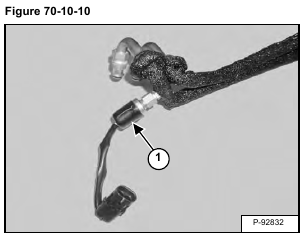
Low Pressure Switch: The low pressure switch (Item 1) [Figure 70-10-10] will disengage the compressor clutch at low pressure readings below 34 – 76 kPa (0,34 – 0,76 bar) (5 – 11 psi) on the low side. The clutch will engage when the pressure is at 117 – 186 kPa (1,2 – 1,9 bar) (17 – 27 psi).
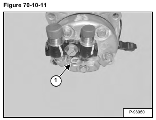
Compressor Relief Valve: The relief valve (Item 1) [Figure 70-10-11] is set at 3502 – 4102 kPa (35 – 41 bar) (508 – 595 psi).
