Raise the loader operator cab. (See Raising The Operator Cab on Page 10-30-1.)
NOTE: The loader control panel is removed for clarity purpose only. The traction lock can be removed without removing the control panel.
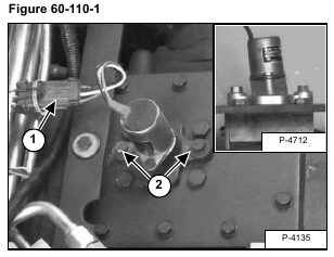
Remove the Do Not Modify sta-strap (P/N 6665527) from the electric solenoid connector (Item 1) [Figure 60-110-1].
Installation: Install a new Do Not Modify sta-strap on the electric solenoid connector.
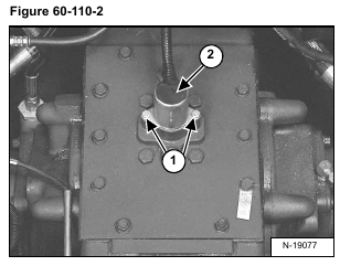
Remove the two mounting bolts (Item 1) [Figure 60-110-2] from the electric solenoid mounting bracket.
Installation: Tighten the mounting bolts to 25-28 ft.-lbs. (34-38 Nm) torque.
Remove the electric solenoid (Item 2) [Figure 60-110-2] from the chaincase cover.
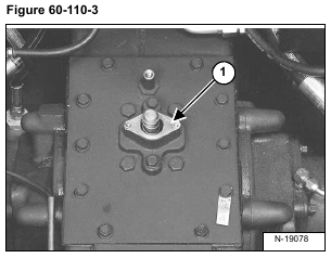
Remove the bracket (Item 1) [Figure 60-110-3] from the chaincase cover.
Installation: Tighten the mounting bolts to 25-28 ft.-lbs. (34-38 Nm) torque.
Be sure the solenoid mounting bracket is installed in the same position. The solenoid mounting surface has a slight angle which tips the top of the solenoid toward the rear of the loader when installed correctly. See inset photo [Figure 60-110-1].
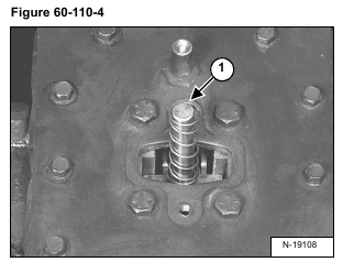
Remove the traction lock assembly (Item 1) [Figure 60-110-4] from the chaincase.
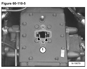
Inspect the guides (Item 1) [Figure 60-110-5] for wear or damage. Replace if necessary .
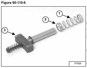
Remove and inspect the compression spring (Item 1) and spring cap washer (Item 2) [Figure 60-110-6] for wear or damage. Replace if necessary. The spring may also stay with the shaft when the electric solenoid and bracket are removed from the chaincase.
Installation: Install the compression spring (Item 1) [Figure 60-110-6] on the collar located on the electric solenoid.
Remove the traction lock assembly (Item 3) [Figure 60-110-6] from the chaincase.
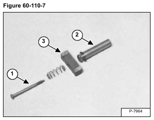
Remove the shaft mounting bolt (Item 1), spring from the assembly shaft (Item 2). Remove the wedge (Item 3) [Figure 60-110-7] and inspect all parts for damage or wear. Replace if necessary.
Installation: Thoroughly clean and dry the shaft mounting bolt (Item 1), the shaft (Item 2) and wedge (Item 3) [Figure 60-110-7]. Use LOCTITE #242 when assembling these parts to the traction lock assembly.
