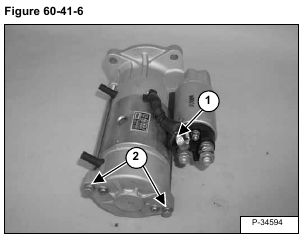
Remove the cable (Item 1) [Figure 60-41-6] from the magnetic switch.
Remove the bolts (Item 2) [Figure 60-41-6].
Installation: Tighten the bolts to 63-129 ft.lbs. (7,1-14,6 Nm) torque.
Remove the armature, yoke, brush holder and rear bracket assemblies (Item 1) from the front assembly (Item 2) [Figure 60-41-7].
NOTE: When separating the parts there will be a steel ball (Item 3) located at the end of the armature shaft (Item 4) [Figure 60-41-7].
Installation: Apply grease to the steel ball (Item 3) and install into the end of the armature shaft (Item 4) [Figure 60-41-7] .
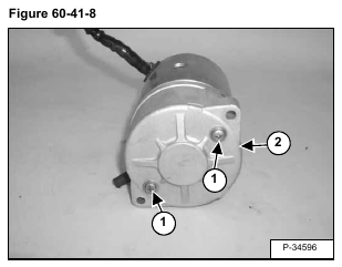
Remove the bolts (Item 1) from the brush cover (Item 2) [Figure 60-41-8].
Remove the cover (Item 2) [Figure 60-41-8].
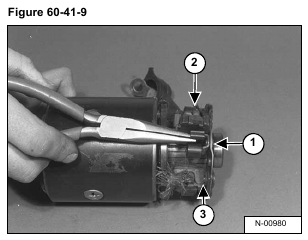
Using a needle nose pliers, pull the brush springs (Item 1) back and remove the brushes (Item 2) [Figure 60-41-9].
NOTE: The brushes are non-replaceable. If the brushes are worn order a new brush holder (for the negative brushes) and yolk (for the positive brushes).
Remove the brush holder (Item 3) [Figure 60-41-9] from the end of the armature.
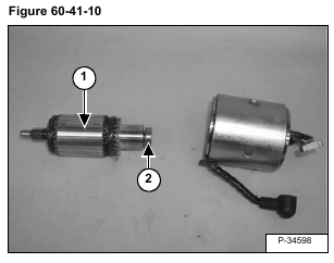
Remove the armature (Item 1) [Figure 60-41-10] from the frame.
Remove the bearing (Item 2) [Figure 60-41-10] from the end of the armature.
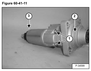
Remove the bolts (Item 1) [Figure 60-41-11] from the magnetic switch.
Installation: Tighten bolts to 34-69 ft.-lbs. ( 3,8-7,8 Nm) torque.
Remove the front assembly (Item 2) from the magnetic switch (Item 3) [Figure 60-41-11].
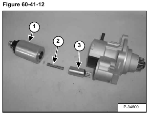
Inspect the magnetic switch (Item 1), the spring (Item 2),and the plunger (Item 3) [Figure 60-41-12] for wear and replace as needed.
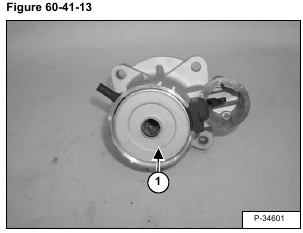
Remove the center bracket (Item 1) [Figure 60-41-13]
Remove the rubber retainer (Item 1) [Figure 60-41-14].
Remove the planetary gears (Item 2) [Figure 60-41-14] and inspect for damage.
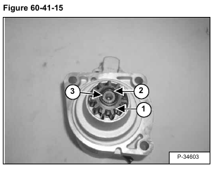
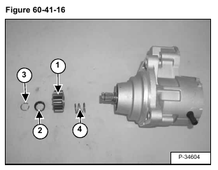
Press down on the pinion (Item 1) [Figure 60-41-15] & [Figure 60-41-16] and retainer (Item 2) [Figure 60-41-15] & [Figure 60-41-16].
Remove the snap ring (Item 3) [Figure 60-41-15] & [Figure 60-41-16]
Remove the retainer (Item 2) [Figure 60-41-15] & [Figure 60-41-16] and pinion (Item 1) [Figure 60-41-15] & [Figure 60-41-16].
Remove the spring (Item 4) [Figure 60-41-16].
Installation: Inspect all parts for wear and replace as needed.
