Clean all parts and apply high temperature grease to the armature bearing, return spring, steel ball, over running clutch, and idler gear rollers.
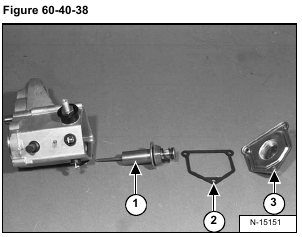
Install the switch plunger (Item 1), gasket (Item 2) and cover (Item 3) [Figure 60-40-38] on the switch housing.
Install the bolts (Item 1) [Figure 60-40-39].
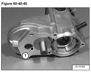
Install the washer (Item 1) [Figure 60-40-40] on the idler gear shaft.
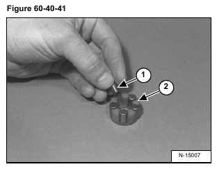
Install the rollers (Item 1) in the retainer (Item 2) [Figure 60-40-41].
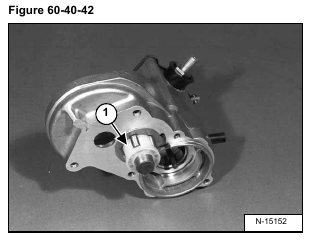
Install the roller/retainer assembly (Item 1) [Figure 60-40-42] on the idler gear shaft.
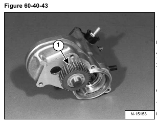
Install the idler gear (Item 1) [Figure 60-40-43] over the retainer.
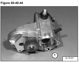
Install the spring (Item 1) [Figure 60-40-44] in the magnetic switch housing.
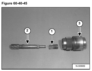
Install the spring (Item 1) over the pinion shaft (Item 2).
Install the pinion shaft (Item 2) in the over running clutch (Item 3) [Figure 60-40-45].
Stand the clutch assembly on end.
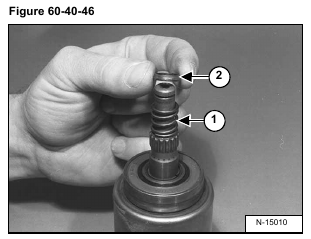
Install the spring (Item 1) and spring seat (Item 2) [Figure 60-40-46] on the pinion shaft.
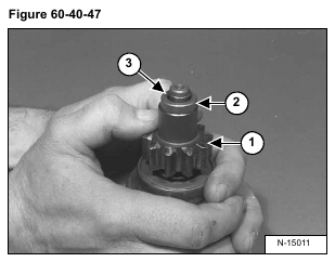
Install the pinion (Item 1) and retainer (Item 2) [Figure 60-40-47] on the pinion shaft.
Press down on the pinion (Item 1) and install the snap ring (Item 3) [Figure 60-40-47] on the pinion shaft.
Pull the retainer (Item 2) over the snap ring (Item 3) [Figure 60-40-47].
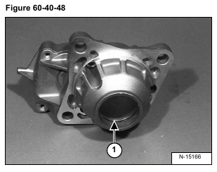
Install the O-ring (Item 1) [Figure 60-40-48] in the starter housing.
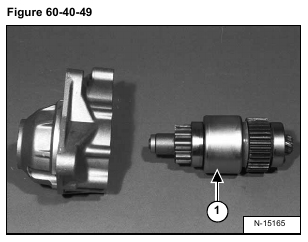
Install the pinion shaft/over running clutch assembly (Item 1) [Figure 60-40-49] in the starter housing.
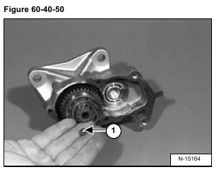
Install the ball (Item 1) [Figure 60-40-50] in the end of the pinion shaft.
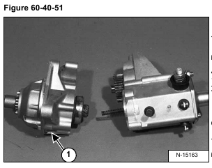
Install the starter housing (Item 1) [Figure 60-40-51] on the magnetic switch housing.
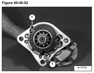
Install the bolts (Item 1) [Figure 60-40-52] in the starter housing. Tighten the bolts to 60-104 in.-lbs. (6,7-11,8 Nm) torque.
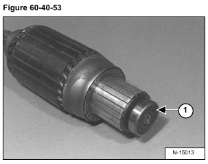
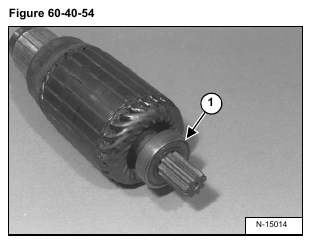
Install the bearings (Item 1) [Figure 60-40-53] & [Figure 60-40-54] on both ends of the armature.
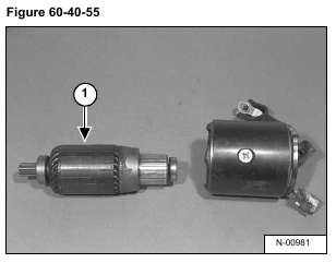
Install the armature (Item 1) [Figure 60-40-55] in the frame.
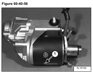
Install the frame/armature assembly (Item 1) [Figure 60-40-56] on the housing.
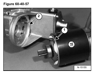
NOTE: Make sure the notch (Item 1) in the frame matches up with the notch (Item 2) [Figure 60-40-57] in the housing.
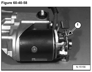
Install the brush holder (Item 1) [Figure 60-40-58] on the end of the armature.
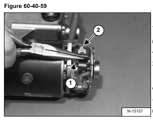
Using the needle nose pliers, pull the brush springs (Item 1) back and install the brushes (Item 2) [Figure 60-40-59].
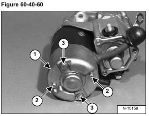
Install the brush cover (Item 1) and bolts (Item 2) [Figure 60-40-60]. Tighten the bolts to 23-40 in.-lbs. (3,0-5,0 Nm) torque.
Install the thru bolts (Item 3) [Figure 60-40-60]. Tighten the bolts to 60-104 in.-lbs. (7-12 Nm) torque.
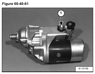
Install the cable (Item 1) [Figure 60-40-61] on the magnetic switch. Tighten the nut to 18-26 ft.-lbs. (24-35 Nm) torque.
