Tilt the Bob-Tach forward, so it is parallel to the floor. Put blocks (approximately 3 inches) under each side of the Bob-Tach [Figure 50-41-1].
Lower the Bob-Tach onto the blocks.
Remove the hoses on the cylinder fittings (Item 1) [Figure 50-41-1].
Remove the hose clamp on the hoses and use the bolt (Item 2) [Figure 50-41-1] on the Bob-Tach lever to
secure the clamp.
Remove the retainer bolt (Item 1) [Figure 50-41-2] and nut from the tilt cylinder rod end pin.
Installation: Tighten the retainer bolt and nut to 18-20 ft.-lbs. (24-27 Nm) torque.
Remove the pivot pin (Item 2) [Figure 50-41-2] from the tilt cylinder rod end.
Remove the tilt cylinder rod end (Item 3) [Figure 50-41-2] from the Bob-Tach.
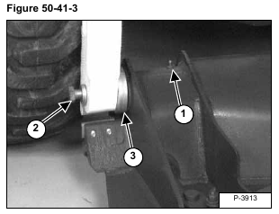
Remove the grease fitting (Item 1) [Figure 50-41-3] (Both sides). This will allow grease to come out in the next step. Not letting grease escape will prevent the pin from going into the Bob-Tach far enough to remove the Bob-Tach from the lift arms.
Loosen the bolt (Item 2) [Figure 50-41-3] at the Bob-Tach pivot pin. (Both sides)
Strike the head of the bolt (Item 2) [Figure 50-41-3] to push the pivot pin into the Bob-Tach frame. (Both sides)
Remove the bolt. (Both sides)
Installation: A longer bolt will be needed to reach through the lift arms into the pins to seat them into the lift
arms. Tighten the bolts to 175-190 ft.-lbs. (240-255 Nm) torque.
Use a punch to push the pivot pins all the way inside the Bob-Tach frame.
Remove the Bob-Tach from the lift arms.
Remove the dust cup (Item 3) [Figure 50-41-3] (Both sides) when the Bob-Tach is free from the loader.
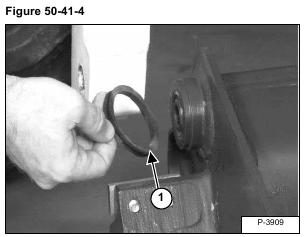
Remove the rubber seal (Item 1) [Figure 50-41-4] (Both sides).
Installation: Use a new seal when assembling.
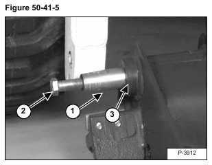
Remove the Bob-Tach pivot pin (Item 1). (Both sides) Thread the bolt (Item 2) [Figure 50-41-5] into the pivot
pins and pull.
Check for wear and damage on the pins and the Bob-Tach bushings (Item 3) [Figure 50-41-5]. Replace as needed.
Installation: Reverse the removal procedure to install the Bob-Tach.


