Lift and block the loader. (See LIFTING AND BLOCKING THE LOADER on Page 10-10-1.)
Raise the lift arms and install an approved lift arm support device. (See Installing Lift Arm Support Device
on Page 10-20-1.)
Stop the engine. Raise the seat bar.
Raise the operator cab. (See Raising The Operator Cab on Page 10-30-1.)
Clean the area around the control valve.
Drain the hydraulic reservoir. (See Replacing Hydraulic Fluid on Page 10-120-3.)
Mark all tubelines for correct installation.
Cap and plug all hoses, tubelines, and fittings.
Remove the control panel. (See Removal and Installation on Page 50-100-1.)
Open the rear door.
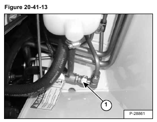
The fixed end main valve hose assembly (Item 1) [Figure 20-41-13] is connected to a fixed end fitting on the
control valve. The hose is routed to the back upright where the hose is connected to a tee fitting that feeds
the base end of both lift cylinders. The hose must be removed at the back tee fitting, located in the right side
upright.
NOTE: Remember the hose routing for ease of control valve installation.
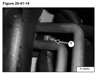
Remove the tubeline clamp (Item 1) [Figure 20-41-14] holding the fixed end main valve hose. The clamp is
located behind fuel fill tube.
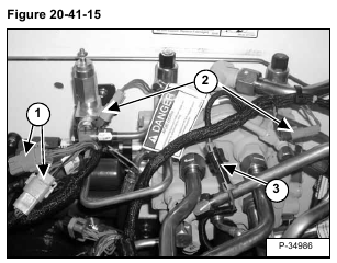
Label and disconnect the actuator electrical connectors (Item 1) [Figure 20-41-15].
Label and disconnect the electrical connectors (Item 2) [Figure 20-41-15].
Label and disconnect the BICSTM electrical connector (Item 3) [Figure 20-41-15].
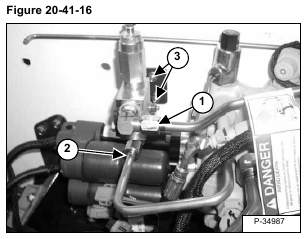
Disconnect the tubeline (Item 1) [Figure 20-41-16] from the lift arm by-pass valve.
Remove the drain tubeline (Item 2) [Figure 20-41-16] from the lift arm by-pass valve.
Remove the bolts (Item 3) [Figure 20-41-16] from the lift arm by-pass control valve bracket.
Remove the lift arm by-pass control valve from the loader.
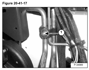
Remove the tubeline clamp (Item 1) [Figure 20-41-17] on the left fender to allow the auxiliary tubelines to move
during the removal and installation of the control valve.
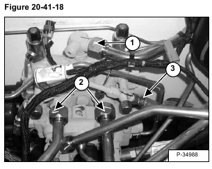
Disconnect the outlet tubeline (Item 1) [Figure 20-41-18] from the control valve.
Disconnect the tubeline (Item 2) [Figure 20-41-18] from the auxiliary section of the control valve.
Disconnect the drain hose (Item 3) [Figure 20-41-18] from the control valve.
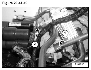
Disconnect the tilt tubeline (Item 1) [Figure 20-41-19] from the control valve.
Disconnect the drain hose (Item 2) [Figure 20-41-19] from the control valve.
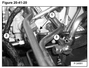
Disconnect the drain hose (Item 1) [Figure 20-41-20] from the control valve.
Disconnect the lift tubeline (Item 2) [Figure 20-41-20] from the control valve.
Disconnect the tilt tubeline (Item 3) [Figure 20-41-20] from the control valve.
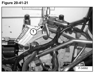
Connect a hoist to the control valve (Item 1) [Figure 20-41-21].
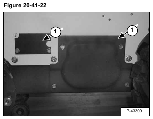
Remove the access covers (Item 1) [Figure 20-41-22] on the right side of the loader frame.
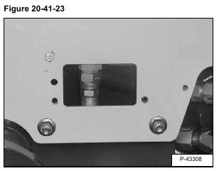
Disconnect the inlet hose from the control valve through the access slot [Figure 20-41-23].
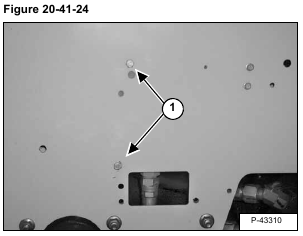
Remove the two control valve mounting bolts/nuts (Item 1) [Figure 20-41-24] from the loader frame.
Remove the control valve from the loader.
Installation: Tighten the mounting bolt & nut to 18-20 ft.-lbs. (24-27 Nm) torque.
Reverse the removal procedure to install the control valve.
