Remove the male coupler (Item 1) [Figure 20-121-2] & [Figure 20-121-3].
Installation: Tighten the male coupler (Item 1) [Figure 20-121-2] & [Figure 20-121-3] to 59 ft.lbs. (80 Nm)
Remove the drain coupler (Item 2) [Figure 20-121-2] & [Figure 20-121-3].
Installation: Tighten the drain coupler (Item 2) [Figure 20-121-2] & [Figure 20-121-3] to 37 ft.lbs. (50 Nm)
Remove the female coupler (Item 3) [Figure 20-121-2] & [Figure 20-121-3].
Installation: Tighten the female coupler (Item 3) [Figure 20-121-2] & [Figure 20-121-3] to 59 ft.lbs. (80 Nm)
Remove the fittings (Item 4), check the O-rings (Item 5) [Figure 20-121-3] and replace as needed.
Remove the springs (Item 6) [Figure 20-121-3].
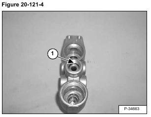
Check the O-ring (Item 1) [Figure 20-121-4] for damage and replace as needed.
Press center of male couplers down and check the O-ring (Item 1) [Figure 20-121-5] for damage and replace as needed.
Check the O-rings (Item 1) backup O-rings (Item 2) [Figure 20-121-6] for damage and replace as needed.
Check the O-rings (Item 1) backup O-rings (Item 2) [Figure 20-121-7] for damage and replace as needed.


