Put jackstands under the rear corners of the loader.
Raise the lift arms and install an approved lift arm support device. (See Installing Lift Arm Support Device on Page 10-20-1.)
Raise the operator cab. (See Raising The Operator Cab on Page 10-30-1.)
Drain the hydraulic reservoir. (See Replacing Hydraulic Fluid on Page 10-120-3.)
Disconnect the steering linkage. (See Linkage Removal And Installation on Page 50-110-3.)
Remove the battery from the loader. (See Removal And Installation on Page 60-20-1.)
Drain the engine coolant from the cooling system. (See RADIATOR on Page 70-50-1.)
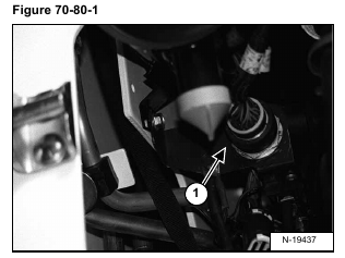
Disconnect the engine harness connector (Item 1) [Figure 70-80-1] from the harness. If there is no connector, remove the harness from the engine.
Remove the air cleaner. (See Removal And Installation on Page 70-40-1.)
Remove the muffler. (See Removal And Installation on Page 70-30-1.)
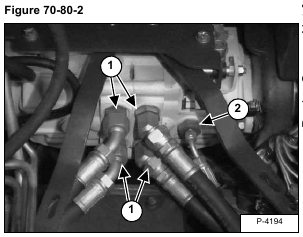
Mark the four drive motor hoses (Item 1) [Figure 70-80-2] for correct installation.
Disconnect the four drive motor hoses (Item 1) [Figure 70-80-2] from the hydrostatic pump.
Disconnect the motor case drain hose (Item 2) [Figure 70-80-2] from the hydrostatic pump.
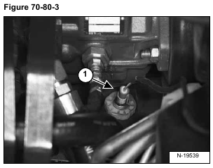
Disconnect the wire harness connector (Item 1) [Figure 70-80-3] from the fuel level sender on the fuel tank.
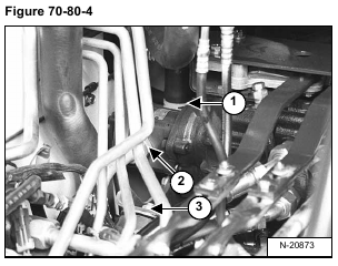
Disconnect the INLET hose (Item 1) [Figure 70-80-4] from the fitting on the hydraulic pump.
Disconnect the outlet tube line (Item 2) [Figure 70-80-4] to the main control valve, from the fitting on the hydraulic pump.
Remove the mounting bolt (Item 3) [Figure 70-80-4] and nut from the right front engine mount.
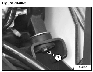
Remove the mounting bolt (Item 1) [Figure 70-80-5] and nut from the left front engine mount.
Installation: Tighten the mounting bolts to 70 ft.-lbs. (95 Nm) torque.
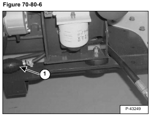
Disconnect the hand pump (Item 1) [Figure 70-80-6] from the fuel line connected to the fuel tank. Cap the fuel lines.
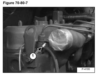
Disconnect the fuel return hose (Item 1) [Figure 70-80-7] from the injector.
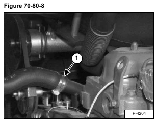
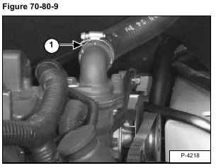
Disconnect the radiator hoses (Item 1) [Figure 70-80-8] & [Figure 70-80-9] from the engine.
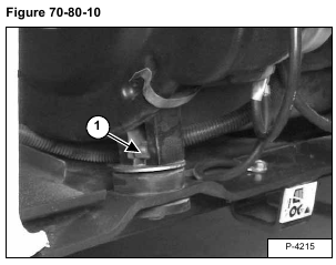
Remove the mounting bolt and nut (Item 1) [Figure 70-80-10] from the left rear engine mount.
Installation: Tighten the mounting bolt to 70 ft.-lbs. (95 Nm) torque.
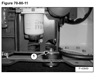
Remove the mounting bolt and nut (Item 1) [Figure 70-80-11] from the right rear engine mount.
Installation: Tighten the mounting bolt to 70 ft.-lbs. (95 Nm) torque.
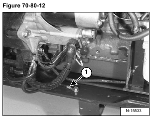
Disconnect the ground cable (Item 1) [Figure 70-80-12] from the loader frame.
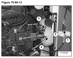
Disconnect the rear light harness connectors (Item 1) [Figure 70-80-13] from the engine harness.
Remove the belt shield mounting bolts (Item 2) [Figure 70-80-13].
Installation: Tighten the mounting bolts to 25-28 ft.-lbs. (34-38 Nm) torque.
Remove the belt shield.
Disconnect the engine speed control rod (Item 3) [Figure 70-80-13] from the linkage.
Remove the coolant overflow bottle (Item 4) [Figure 70-80-13].
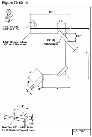
A tool needs to fabricated to be used in the removal procedure. This tool allows the engine/hydrostatic pump assembly to be lifted evenly for easier removal. Use the dimensions shown in [Figure 70-80-14] to make the engine removal tool.
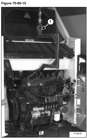
Install the chain hoist on the eyelet (Item 1) [Figure 70-80-15] of the removal tool.
Fasten a chain to other end of the removal tool with two bolts as shown in [Figure 70-80-15].
Fasten securely one end of the chain to one of the lifting brackets on the engine [Figure 70-80-15].
Fasten securely the other end of the chain to the other lifting bracket on the engine [Figure 70-80-15].
NOTE: You may need to adjust the chain which fastens to the engine a couple of times to reach the correct lifting position.
Remove the engine/hydrostatic pump assembly from the loader.
Reverse the removal procedure to install the engine.
