Clean the area around the injection pump thoroughly.
Disconnect the high pressure fuel lines (Item 1) [Figure 70-70-15] from the fuel injectors.
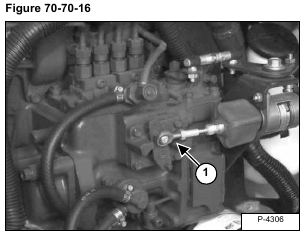
Disconnect the fuel shut-off linkage (Item 1) [Figure 70-70-16].
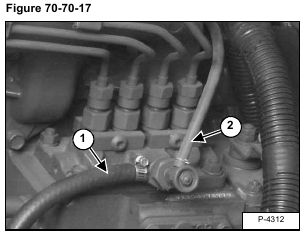
Disconnect the fuel inlet hose (Item 1) and the fuel return hose (Item 2) [Figure 70-70-17] from the injection pump vent.
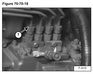
Cap the inlets on the injection pump vent where the hoses were removed [Figure 70-70-18].
Remove the high pressure fuel lines (Item 1) [Figure 70-70-18] from the injection pump.
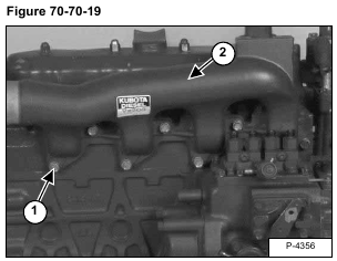
Remove the seven mounting bolts (Item 1) from the intake manifold (Item 2) [Figure 70-70-19].
Installation: Tighten the mounting bolts to 16-20 ft.-lbs. (22-27 Nm) torque.
Remove the intake manifold from the engine.
Installation: Replace the manifold gasket if it is worn or damaged.
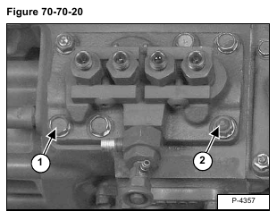
Remove the four mounting bolts (Item 1) and two nuts (Item 2) [Figure 70-70-20] from the injection pump.
Installation: Tighten the mounting bolts to 16-20 ft.-lbs. (22-27 Nm) torque.
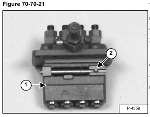
Remove the injection pump (Item 1) [Figure 70-70-21] and shim(s) from the engine.
NOTE: The pin (Item 2) [Figure 70-70-21] located on the control rack, needs to be installed correctly during installation. (See Fuel Injection Pump Removal And Installation (Cont’d) on Page 70-70-8.) for correct installation.
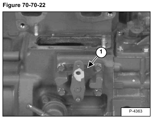
Remove the side cover (Item 1) [Figure 70-70-22] from the injection pump chamber.
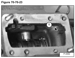
Be sure the spring (Item 1) [Figure 70-70-23] is located in the injection pump chamber as shown.
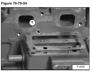
Install the shim(s) (Item 1) [Figure 70-70-24] on the injection pump mounting surface. (See Timing The Injection Pump on Page 70-70-9.) for information on number of shims used.
Install the injection pump in the engine.
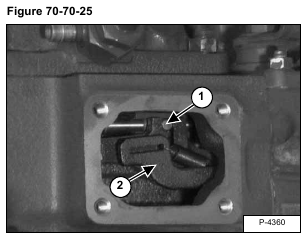
Put the pin (Item 1) on the control rack in the slot of the fork lever (Item 2) [Figure 70-70-25] located inside the injection pump chamber.

