Raise the loader lift arms and install an approved lift arm support device. (See Installing Lift Arm Support Device on Page 10-20-1.)
Lift and block the loader. (See LIFTING AND BLOCKING THE LOADER on Page 10-10-1.)
Raise the loader operator cab. (See Raising The Operator Cab on Page 10-30-1.)
Drain the fluid from the chaincase. (See Removing The Oil on Page 40-30-1.)
Remove the engine speed control. (See Removal And Installation on Page 70-20-1.)
Remove the control panel. (See Removal and Installation on Page 50-100-1.)
Remove the traction lock assembly. (See TRACTION LOCK on Page 60-110-1.)
Remove the center chaincase cover. (See Center Cover Removal And Installation on Page 40-30-3.)
Remove the front (or rear) chaincase cover. (See CHAINCASE on Page 40-30-1.)
Remove the front (or rear) axle and sprocket. (See DRIVE COMPONENTS on Page 40-20-1.)
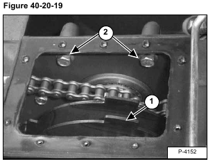
Remove the parking brake disc (Item 1) [Figure 40-20-19]. (See Disc Removal And Installation on Page 40-10-2.)
Remove the six carrier mounting bolts (Item 2) [Figure 40-20-19] from inside the chaincase.
Installation: Tighten the motor carrier mounting bolts to 125-140 ft.-lbs. (170-190 Nm) torque.
Tip the end of the sprocket on the motor carrier toward the rear of the loader and remove the rear drive chain from the sprocket.
NOTE: It may be necessary to tie the front drive chain up as shown in photo [Figure 40-20-20], so the
carrier/motor assembly can be moved enough to free the rear drive chain (Item 1) [Figure 40-20-20] from the sprocket.
Remove the front drive chain from the chaincase.
The tool listed is needed for the following procedure:
MEL1037 – Chain Link Tool
Installation: If a new chain is installed, a connector link must be used to connect the chain together.
Use MEL1037 Chain Link Tool and #80 chain adapter.
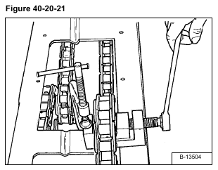
Secure the tool and place the connector link in the tool as shown [Figure 40-20-21].
Turn the threaded rod of the tool and press the connector link together on the chain [Figure 40-20-21]. Tighten the
threaded rod of the chain link tool to 130 ft.-lbs. (176 Nm) torque.


