The following tool listed will be needed to do the following procedure:
MEL1563 – Remote Start Tool Kit
Connect the remote start tool to the engine harness. (See REMOTE START on Page 10-60-1.)
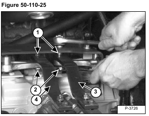
Loosen the nut (Item 1) a couple of turns, then loosen the bolt (Item 2). The bolt (Item 2) is threaded into the linkage bars (Items 3 & 4) [Figure 50-110-25].
The bolt (Item 2) [Figure 50-110-25] must be loose enough to allow the torsion bushing to turn freely between the pintle arm and the linkage bar.
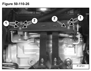
Loosen the four bolts (Item 1) [Figure 50-110-26] holding the two centering blocks. Move the right hand centering
block to the right as far as possible.
NOTE: Bolt holes (Item 2) [Figure 50-110-26] are slotted for pintle arm centering adjustment.
Adjust the left centering block first [Figure 50-110-27].
Start the engine and run at high RPM.
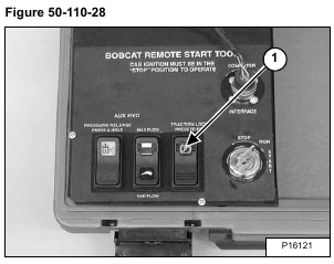
Move the traction lock override switch (Item 1) [Figure 50-110-28] to the OFF position so the traction function is unlocked. The wheels are now able to turn.
Move the left control lever until the tires do not turn (neutral position).
Move the left centering block to the left until it contacts both pintle cams and the control lever is still in the neutral position [Figure 50-110-27].
Tighten the bolts to 25-28 ft.-lbs. (34-38 Nm) torque.
NOTE: If the centering blocks are worn, they can be removed and rotated 180 degrees and reinstalled. If the cams are worn, they can be loosened and rotated 90 degrees and reinstalled.
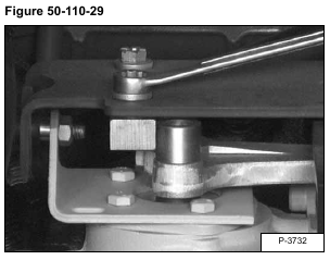
Adjust the right centering block [Figure 50-110-29].
Move the right control lever until the tires do not turn (neutral position).
Move the right centering block to the left until it contacts both pintle cams and the control lever is still in the neutral
position [Figure 50-110-29].
Tighten the bolts to 25-28 ft.-lbs. (34-38 Nm) torque.
Test both levers by moving them backward and forward and letting them return to neutral by the return spring force.
If the levers do not return to neutral and the tires do not come to a complete stop, repeat the adjustment procedure again.
Stop the engine.
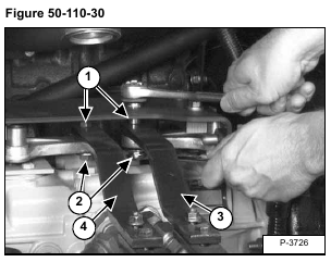
Tighten the two bolts (Item 1) to 11-13 ft.-lbs. (15-17 Nm) torque, then tighten the two nuts (Item 2) [Figure 50-110-
30] to 25-28 ft.-lbs. (34-38 Nm) torque.
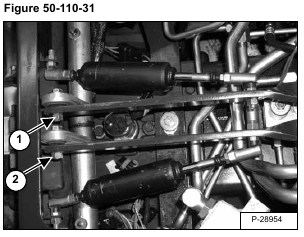
Tighten the two bolts to 11-13 ft.-lbs. (15-17 Nm) torque, then tighten the two nuts to 25-28 ft.-lbs. (34-38 Nm)
torque at the steering cross shaft (Items 1 & 2) [Figure 50-110-31].
