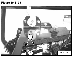
Disconnect the electrical connectors from the control lever [Figure 50-110-5].
Remove the nuts from the two U-bolts (Item 1) [Figure 50-110-5] used to mount the control lever.
Remove the U-bolts from the control lever mount.
Remove the control lever (Item 2) [Figure 50-110-5] by sliding the lever through the rubber boot (Item 1) [Figure
50-110-6] on the front of the control panel.
Installation: Tighten the u-bolts so the lever can not be moved either right or left when seated in the operator
seat. Be sure the control lever does not interfere with the operator cab when lowering or raising the cab.
