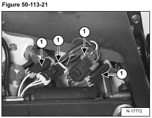
Disconnect the electrical connectors (Item 1) [Figure 50-113-21] from the control lever switch handle.
Remove the electrical connectors from the control lever switch handle. (See ADVANCED CONTROL SYSTEM (ACS) SELECTABLE HAND/FOOT CONTROL on Page 60-123-1.)
Installation: The connectors are color coded, match the colored connectors when assembling.
Loosen the two u-clamps (Item 1) [Figure 50-113-22] nuts.
Installation: Tighten the u-bolts so the lever can not be moved either right or left when seated in the operator
seat. Control lever end (Item 2) [Figure 50-113-22] should be flush with bell crank. Be sure the control lever
does not interfere with the operator cab when lowering or raising the cab. The distance between handles should be
18.25 inches [Figure 50-113-23].
Remove the control lever from the cross shaft and control panel.
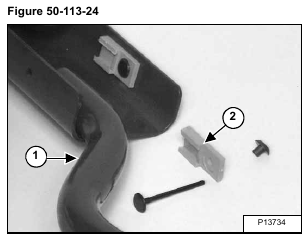
The control lever (Item 1) [Figure 50-113-24] must be replaced as a complete unit.
The connector clip (Item 2) [Figure 50-113-24] can be replaced separately from the control lever.


