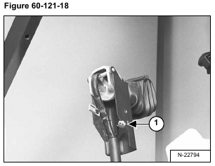
To remove the switch handle, the connector (Item 1) [Figure 60-121-18] must be removed from the wires.
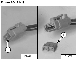
Remove the wedge (Item 1) [Figure 60-121-19] from the connector.
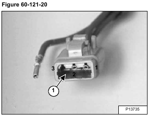
Using a pointed tool, press down on the tab (Item 1) [Figure 60-121-20] and pull the wire from the connector.
Installation: Install the wires into the connector as listed below [Figure 60-121-20]:
Right Control Lever Switch Handle
1-Terminal – Red/White
2-Terminal – Black/White
3-Terminal – Purple/White
Left Control Lever Switch Handle
1-Terminal – Red/White
2-Terminal – Black/White
3-Terminal – Purple/White
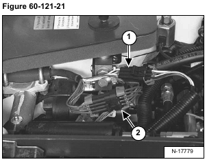
Disconnect the right switch handle connectors (Items 1 & 2) [Figure 60-121-21] from the loader wiring harness connectors.
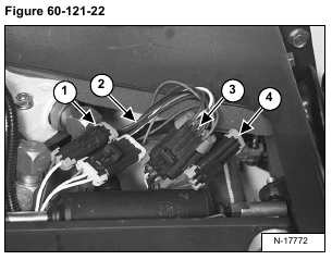
Disconnect the left switch handle connectors (Items 1, 2, 3 & 4) [Figure 60-121-22] from loader wiring harness connectors.
Remove the connector locks and connectors from the wires to remove the switch handle from the control handle.
Installation: The wire colors of the control lever harness are as follows:
Right Switch Handle
Ten-Pin Connector
A-Terminal – Orange
B-Terminal – White
C-Terminal – White/Black
D-Terminal – White/Red
E-Terminal – Dk. Green
F-Terminal – White/Lt. Green
G-Terminal – Blank
H-Terminal – Lt. Green
J-Terminal – Yellow
K-Terminal – Blank
Three-Pin Connector
A-Terminal – Pink/Red
B-Terminal – Pink/Black
C-Terminal – Pink/Lt. Green
Left Switch Handle
Ten-Pin Connector
A-Terminal – Orange
B-Terminal – Dk. Blue
C-Terminal – White
D-Terminal – Purple
E-Terminal – Blank
F-Terminal – Tan
G-Terminal – Pink
H-Terminal – Blank
J-Terminal – Blank
K-Terminal – Blank
Three-Pin Connector
A-Terminal – Red/White
B-Terminal – Black/White
C-Terminal – Purple/White
Two-Pin Connector
A-Terminal – Black
B-Terminal – Red
Five-Pin Connector
A-Terminal – Dk. Green
B-Terminal – Brown
C-Terminal – Blank
D-Terminal – Yellow
E-Terminal – Blank
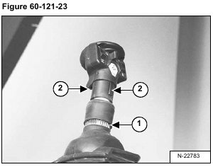
Roll the pistol grip handle cover (Item 1) [Figure 60-121-23] down.
Using a small screwdriver, lift the handle tabs (Item 2)
[Figure 60-121-23] and slightly rotate the switch handle.
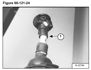
Pull the switch handle and wiring harness assembly (Item 1) [Figure 60-121-24] from the control lever.
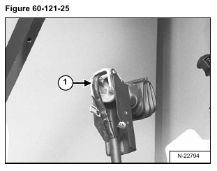
Installation: When installing the switch handle and wiring harness assembly into the control handle, route the harness (Item 1) [Figure 60-121-25] to assure proper return of the control handle to neutral position.
