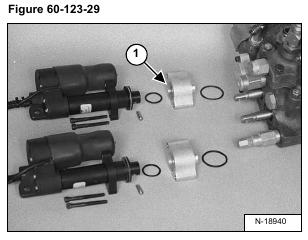
Remove the actuator from the hydraulic control valve.
(See Actuator Removal And Installation on Page 20-41-8.)
Check the mounting block (Item 1) [Figure 60-123-29] and bolts for wear and replace as needed.
Check the actuator wiring harness connector (Item 1) [Figure 60-123-30] and replace if broken.
Installation: Install the wires into the connector as listed below. The terminal numbers are written on the back of the connector (Item 2) [Figure 60-123-30].
Lift and Tilt Actuator
1 – Terminal – Black/Green – Larger diameter wire (16 gauge)
2 – Terminal – Green – Larger diameter wire (16 gauge)
3 – Terminal – Red/Green – Larger diameter wire (16 gauge)
4 – Terminal – Open
5 – Terminal – Red – Smaller diameter wire (18 gauge)
6 – Terminal – Open
7 – Terminal – Open
8 – Black – Smaller diameter wire (18 gauge)

